Installation and commissioning
Instructions for installation and commissioning.
Name, article number and e-number
Name | Article number | E-number (SE) |
|---|---|---|
PoE Switch 8p PS OUT S | PL02P00048P050P-UTS | 51 73 418 |
PoE
[sv] Om
[sv] PoE Switch 8p PS UT S är en strömförsörjning med PoE för utomhusbruk. Byggd för att klara nordiska förhållande - sommar som vinter. Produkten skiljer sig från inomhus-batteribackuper från Milleteknik och vissa funktioner har tillkommit och andra har fallit från.
Revisions and the edition of this document
The current and most recently published edition of this document is available at www.milleteknik.com.
The validity of this document can not be guaranteed, as new editions are published without prior notice.
Original instructions for use: Swedish.[1].
Instructions for use, technical data and translations thereof may contain errors. It is always the responsibility of the installer to install the product in a safe manner.
Symbols
Symbols | Name | Explanation |
|---|---|---|
 | Warning | Risk of electric shock, improper installation or hot surfaces. Appears in some manuals |
 | Note | Used for supplementary information that clarifies the text. |
 | Caution/Important | Indicates the risk of equipment damage or malfunction. Also used for information that is important but not security-related |
 | Tips | Displays practical advice or shortcuts for installation, operation, or service. |
 | CE marking | The product complies with applicable EU directives and harmonised standards. |
 | Read the manual | Please read manual before installation and service. |
 | Do not dispose of in household waste | The product is covered by the WEEE Directive and must not be disposed of with household waste, it must be recycled and delivered to a recycling centre. |
 | Recycling | Packaging, products and other materials that do not contain electronics must be recycled in accordance with local environmental regulations. |
Installation — general information
Installation shall be carried out by a competent electrician in accordance with the applicable national electrical installation rules.
The product is of protection class I and must be connected to a grounded 230 V AC circuit.
A main switch according to IEC 60947-1 shall be provided in the fixed installation. The switch should be easily accessible and clearly marked with its function.
The area of the supply cable shall be at least 1,0 mm² and fitted with a fuse T 2,5 A (slow-blown) or equivalent.
AC and low voltage cables must not be pulled together. Keep separate cable chutes or bundles
Check that protective earth (PE) is properly connected before turning on voltage.
Ensure free air circulation around the enclosure at least 100 mm, unless otherwise specified. Ventilation openings must not be covered.
The product is intended for indoor installation in normal environment (pollution number 2 and indoor class 1).
These general requirements apply to all Milleteknik products with 230 V mains connection.
Requirements for main switch, fuse and cable area
In order to comply with applicable electrical safety requirements, the installation shall be equipped with a main switch according to IEC 60947-1.
Component | Requirements |
|---|---|
Main switch | A main switch according to IEC 60947-1 shall be included in the installation and be easily accessible. Separated phase (L) and neutral (N) |
Fuse | The supply circuit shall be protected by a fuse or automatic fuse with rated current according to the product specification (normally T 2,5 A slow-blow or equivalent). Refer to the device's nameplate. |
Fuses | Approved type according to IEC 60127. |
Cross-sectional area (230 V) | At least 1,0 mm2 |
Cable length | In the case of longer wiring, voltage drops should be taken into account so that the operating voltage does not fall below 230 V ± 10% at the unit. |
Strain relief | All cables must be properly secured and strain relief checked before energizing the unit. |
These requirements apply to all Milleteknik products with 230 V mains connection.
The table below shows recommended cable area for low current installations at different voltages, current strengths and cable lengths. Values are based on copper cable and a maximum voltage drop of approximately 3% to ensure operational reliability.
Enclosures
General assembly instructions
The enclosure shall be mounted vertically.
For good ventilation, at least 100 mm of free space should be provided above and on the sides of the enclosure.
The device should be mounted at a comfortable working height, normally between 1.4 and 1.8 m.
Avoid placement in direct sunlight, near heat sources, or in environments with high humidity or dust.
Installation shall be carried out in accordance with the applicable installation rules and by a competent installer.
Mounting - wall mounting
Recommended distance between screw head and wall should be 1.5-2 mm.
Do not block the flow of air on the sides.
Outdoor mounting on pole
The product is intended for mounting on a pole with rails or corresponding fastening parts.
Use rails and fasteners that are compatible with the weight and mounting pattern of the product.
Install the rails in the product before installing the post brackets or pipe clamps.
Place pipe clamps or corresponding fastening parts around the post and connect them to the mounting points of the rails.
Check that the product is aligned and mounted in a vertical position before tightening.
The diameter and material of the post should be suitable for the selected type of fastening detail.
Tighten all screws and nuts according to the recommendations of the fastening details.
Ensure that the product is firmly fixed and cannot rotate or slide on the post after assembly.
Cable connections should be oriented downwards or according to the specific installation instructions of the product.
Avoid locations where water can flow directly onto the enclosure from surfaces above.
[sv] Monteringshål, avstånd och ø.
[sv] Vikt med batterier
[sv] Nettovikt utan batterier | [sv] Batterityp | [sv] Antal | [sv] Batterier / vikt per styck | [sv] Vikt med batterier |
|---|---|---|---|---|
[sv] - | [sv] 14 Ah | 2 | [sv] 4,2 kg | [sv] Vikt + 8,4 kg |
Outdoor mounting on pole
The product is intended for mounting on a pole with rails or corresponding fastening parts.
Use rails and fasteners that are compatible with the weight and mounting pattern of the product.
Install the rails in the product before installing the post brackets or pipe clamps.
Place pipe clamps or corresponding fastening parts around the post and connect them to the mounting points of the rails.
Check that the product is aligned and mounted in a vertical position before tightening.
The diameter and material of the post should be suitable for the selected type of fastening detail.
Tighten all screws and nuts according to the recommendations of the fastening details.
Ensure that the product is firmly fixed and cannot rotate or slide on the post after assembly.
Cable connections should be oriented downwards or according to the specific installation instructions of the product.
Avoid locations where water can flow directly onto the enclosure from surfaces above.
Mounting on pole
Mounting on pole
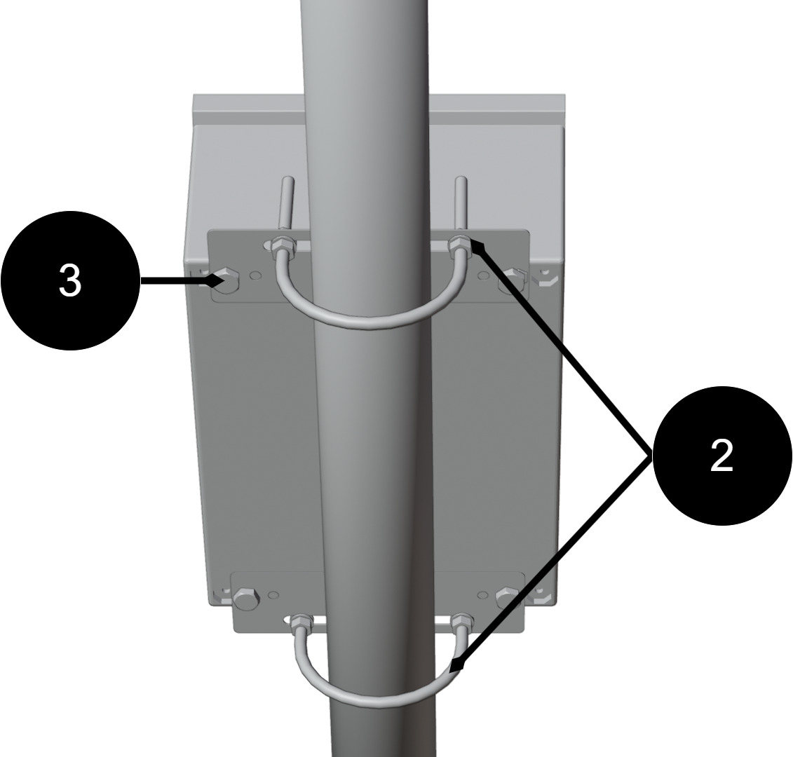
Assemble in this order:
Place the mounting plates (3) on the upper and lower attachment points of the enclosure and attach them lightly with the screws provided. Do not tighten finally yet.
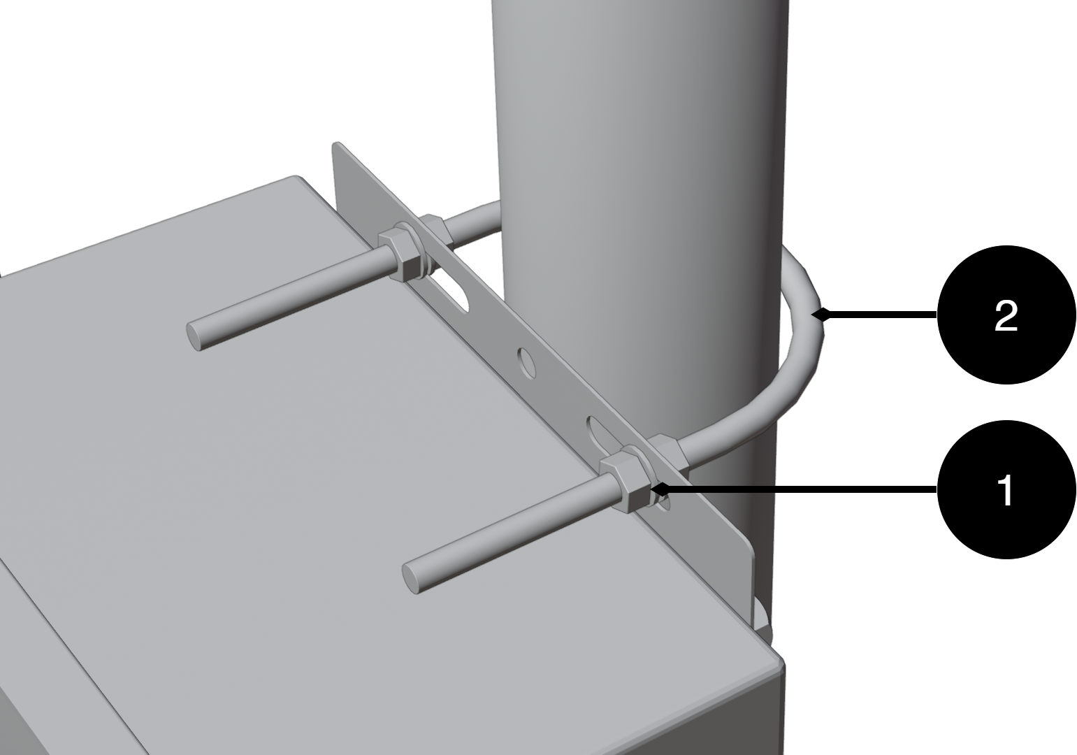
Pass the lower U-bolt (2) around the post and through the holes in the lower mounting plate. Install washers and nuts. Tighten lightly.
Pass the upper U-bolt (2) around the post and through the holes in the upper mounting plate. Install washers and nuts
Adjust the position of the enclosure so that it is in solder and centered toward the post.
Tighten all nuts in sequence: — lower U-bolt — upper U-bolt — screws to the mounting plates
Check the attachment by lightly loading the enclosure forward/backward to ensure stable mounting.
Component overviews
Component Overview Mounting Kits
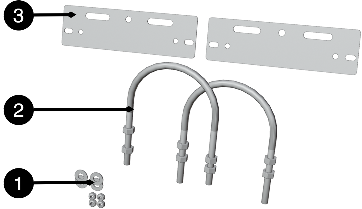
No. | Explanation |
|---|---|
1 | Fixing plate |
2 | U-bolt for pole |
3 | Washers and nuts |
Component overviewNOVA FLX L
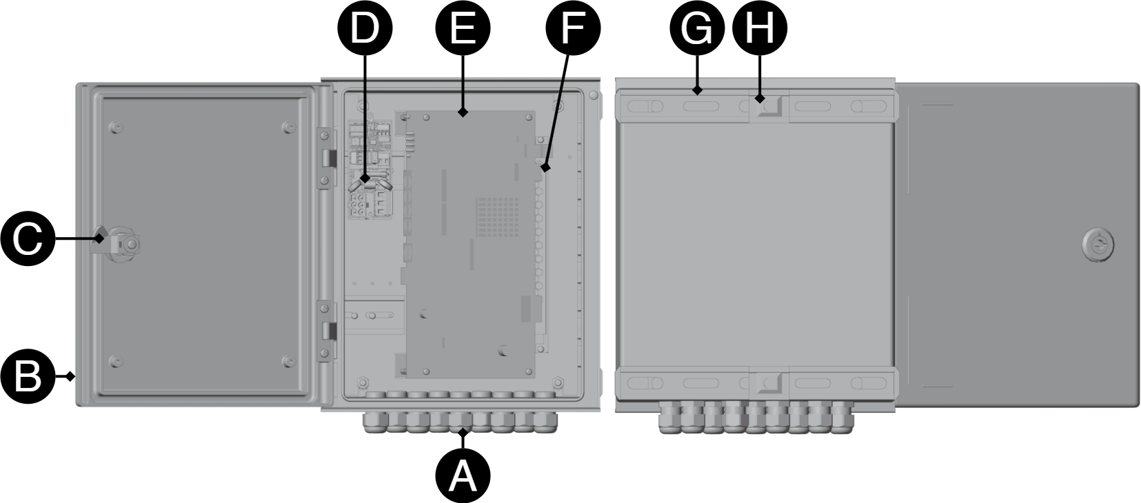
Letter | Explanation |
|---|---|
A | Cable grommets. |
B | Door. |
C | Lock. |
D | Plugging/lightning protection board. |
E | Poe card. |
F | Power supplies. |
G | Bracket on the back. |
H | Fastening screw. |
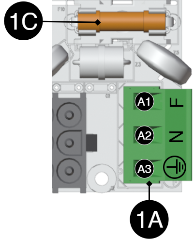
[sv] Kortbeskrivning 230 V inkoppling, 24 V DC ut och åskskydd
![[sv] Kortet är tredelat och kan delas upp för att erhålla önskad funktion.](image/uuid-e2fb4779-efe7-ab4e-8c1d-93079cc3d00b.png)
[sv] Kortet har tre delar, det är inte säkert att alla konfigurationer har alla delar av kortet.
[sv] Beteckning | [sv] Förklaring | |
|---|---|---|
[sv] 1A | [sv] Inkoppling 230 V AC inkommande. | |
[sv] A1 | [sv] Fas (F) | |
[sv] A2 | [sv] Neutral (N) | |
[sv] A3 | [sv] Jord (PE) | |
[sv] 1B | [sv] Inkoppling till nätaggregat. | |
[sv] 1C | [sv] Nätsäkring. | |
[sv] Beteckning | [sv] Förklaring | |
|---|---|---|
[sv] 2D | [sv] 24 V DC strömmatning från nätaggregat. | |
[sv] 2E | [sv] Larm | |
[sv] E1 | [sv] NC | |
[sv] E2 | [sv] COM | |
[sv] E3 | [sv] NO | |
[sv] 2F | [sv] 24 V ut. | |
[sv] F1 | - | |
[sv] F2 | + | |
[sv] Beteckning | [sv] Förklaring | |
|---|---|---|
[sv] 3G | [sv] 24 V DC in | |
[sv] G1 | - | |
[sv] G2 | + | |
[sv] G3 | [sv] PE | |
[sv] 3H | [sv] Extern jordanslutning (i kapsling/jord). | |
[sv] 3I | [sv] Larm | |
[sv] I1 | [sv] NO | |
[sv] I2 | [sv] COM | |
[sv] I3 | [sv] NC | |
[sv] 3J | [sv] Potentiometer, ställbar +/- | |
[sv] 3K | [sv] LED, lyser gult vid jordfel. | |
[sv] Inkoppling av strömmatning
[sv] 230 V kopplas in på plint 1A.
[sv] Anslut matningsspänning, 230 V AC
[sv] Matningsspänning kopplas in på plinten.
[sv] Beteckning | [sv] Förklaring | |
|---|---|---|
[sv] 1A | [sv] Inkoppling 230 V AC inkommande. | |
[sv] A1 | [sv] Fas (F) | |
[sv] A2 | [sv] Neutral (N) | |
[sv] A3 | [sv] Jord (PE) | |
[sv] 1C | [sv] Nätsäkring. | |
[sv] Driftsättning - hur enheten skall startas
Danger
Personal injury or death can occur if the device is connected to the mains or live when disassembling / moving.
[sv] Anslut last.
[sv] Anslut nätspänning.
[sv] Koppla in nätspänning.
Maintenance
The system with the exception of batteries is maintenance-free when installed in an indoor environment.
Product sheet - power supply / battery backup
Product sheet - power supply from Milleteknik
PoE
Name, article number and e-number
Name | Article number | E-number (SE) |
|---|---|---|
PoE Switch 8p PS OUT S | PL02P00048P050P-UTS | 51 73 418 |
Area of use
Power supply to power PoE devices such as surveillance cameras and other PoE powered devices.
Long life, energy efficient and support is available if something goes wrong, now or in 10 years.
Common uses
Supports IP cameras, readers, door centers and other networked security devices
Power and data distribution over a single network cable for simplified installation.
Used to power IP-based access systems where both data and power go through network cabinets.
Technical description
PoE switch with eight PoE fed ports and two LAN ports and one sfp port. Power supplies power PoE cards. The device lacks batteries, so backup power in case of power failure is not possible
Voltage, current and power
Mains voltage: 230 V AC - 240 V AC, 47 Hz - 63 Hz.
Power: 240W and 30.8W per port. 48V power supply directly from power supply.
[sv] Extra utspänning, 24 V. 8,5 A / 200W.
Load outputs
PoE switch can drive load to PoE devices and external power supply can drive one (1) 24 V load output to power other applications.
Protection
Protection against: Overvoltage, overtemperature and short circuit.
Indications and communication
Communication via software in switch. Indications on LEDs on switch
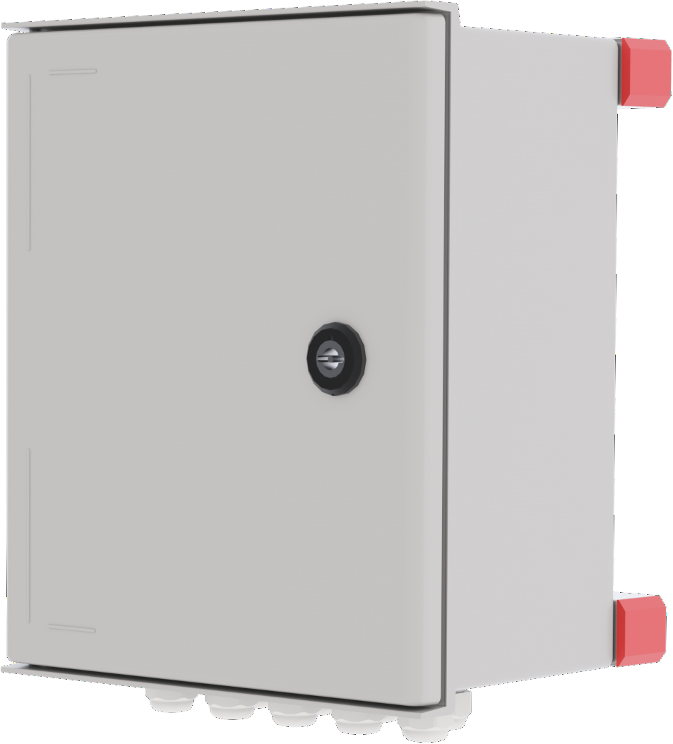
Enclosure
Box in fiberglass reinforced acrylic plastic.
Weight
Name | Net weight | Weight incl. packaging |
|---|---|---|
PoE Switch 8p PS OUT S | - | - |
Installation requirements
The device is intended for fixed installation. Ambient temperature: – 15°C to +35°C.
Requirements that the product meets
EMC: | EMC Directive 2014 / 30EU |
Electricity: | Low voltage directive: 2014/35 / EU |
CE: | EC Directive in force: 765/2008 |
Emissions: | |
Immunity: | EN61000-6-2:2005, EN61000-4-2, -3, 4, -5, -6, -11 SS-EN 50 130-4:2011 Edition 2, EN50131-6 |
Machinery Directive | The product is part of electrical systems, is subject to the relevant electrical and safety directives and is not a machine according to the Machinery Directive (2006/42/EC). |
Ecodesign | Milleteknik's products are intended for professional use and are therefore not directly covered by the Ecodesign Regulation (EU 2019/1782). As some components may be covered, we nevertheless disclose relevant information to give our customers confidence in their choice |

Guarantee
Expandable, options and accessories
The product cannot be expanded.
Manufacturing, lifespan, environmental impact and recycling
Manufactured by Milleteknik in Partille, Sweden.
Link to technical specifications
Links to manuals and product sheets
You can find manuals and product sheets at: www.milleteknik.se The QR code below takes you to the product page.
Name | Dimensions | Batteries that fit | Link |
|---|
Batteries are only included if specified, otherwise batteries will need to be purchased separately.
Miscellaneous
The difference between PoE, PoE+ and PoE++.
About this information
All information is published subject to possible errors. Information is updated without prior notice. |
Publication date 2026-03-10
Address and contact details
Milleteknik AB |
Ögärdesvägen 8 B |
S-433 30 Partille |
Sweden |
+46 31 340 02 30 |
info@milleteknik.se |
www.milleteknik.com |
[1] Translations in languages other than Swedish are indicative only and not verified. Translation should always be checked against the Swedish original to ensure accurate information