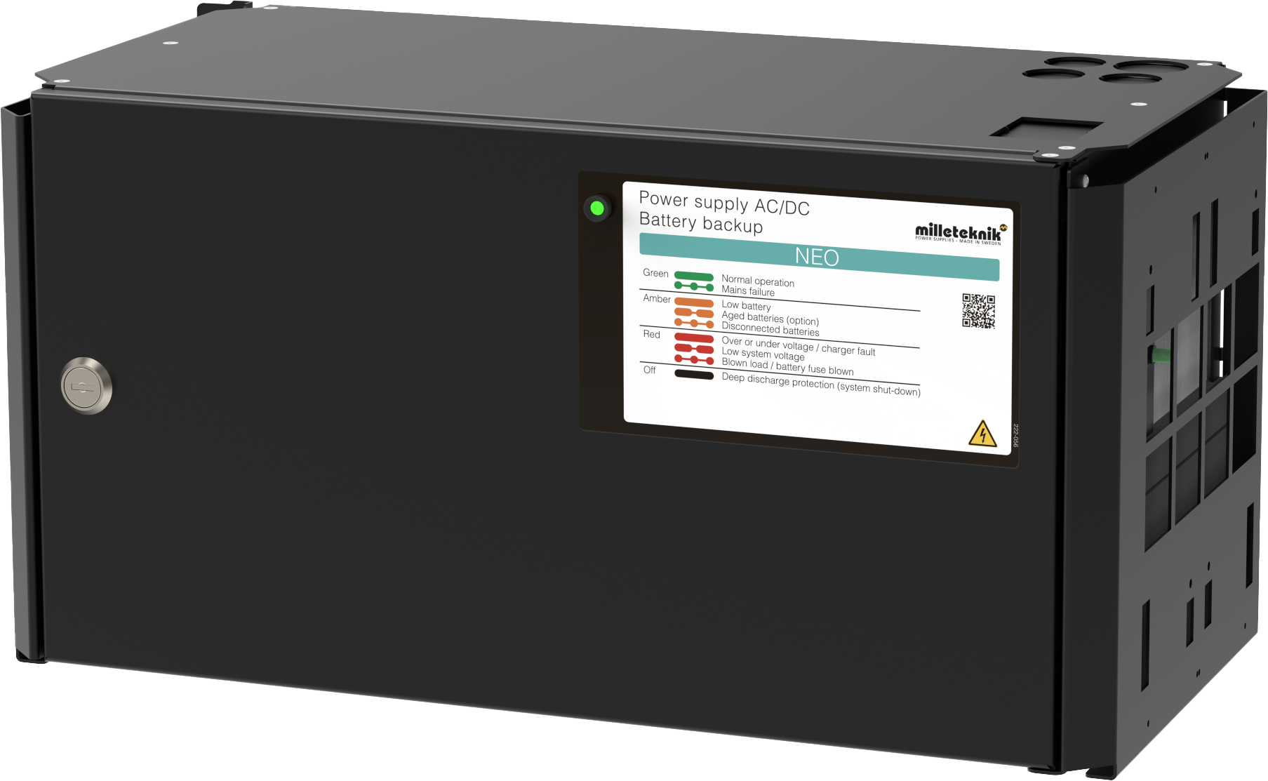
About NEO
NEO is normally used in security systems where the requirements are higher for more functions, alarm functions, longer backup operating times or when the battery backup is to handle higher loads.
About translation of this document
User manual and other documents are in the original language in Swedish. Other languages may be machine translated and/or not reviewed, errors may occur.
Steps for installation and deployment
The unit must be installed and deployed in the following order:
Installation of the device.
Connecting batteries.
Connection of load.
Connection of communication or to external alarm. If communication / external alarm is not required or if the device cannot communicate - skip this step.
Mains connection.
Commissioning
Caution
When the mains is connected, the unit is put into operation. Therefore connect the electrical network (mains) last to avoid faults on other equipment that is connected on load or over communication. The unit also does not register batteries if they are connected after the mains has been connected.
Component overviews
Component overviewNOVA FLX M
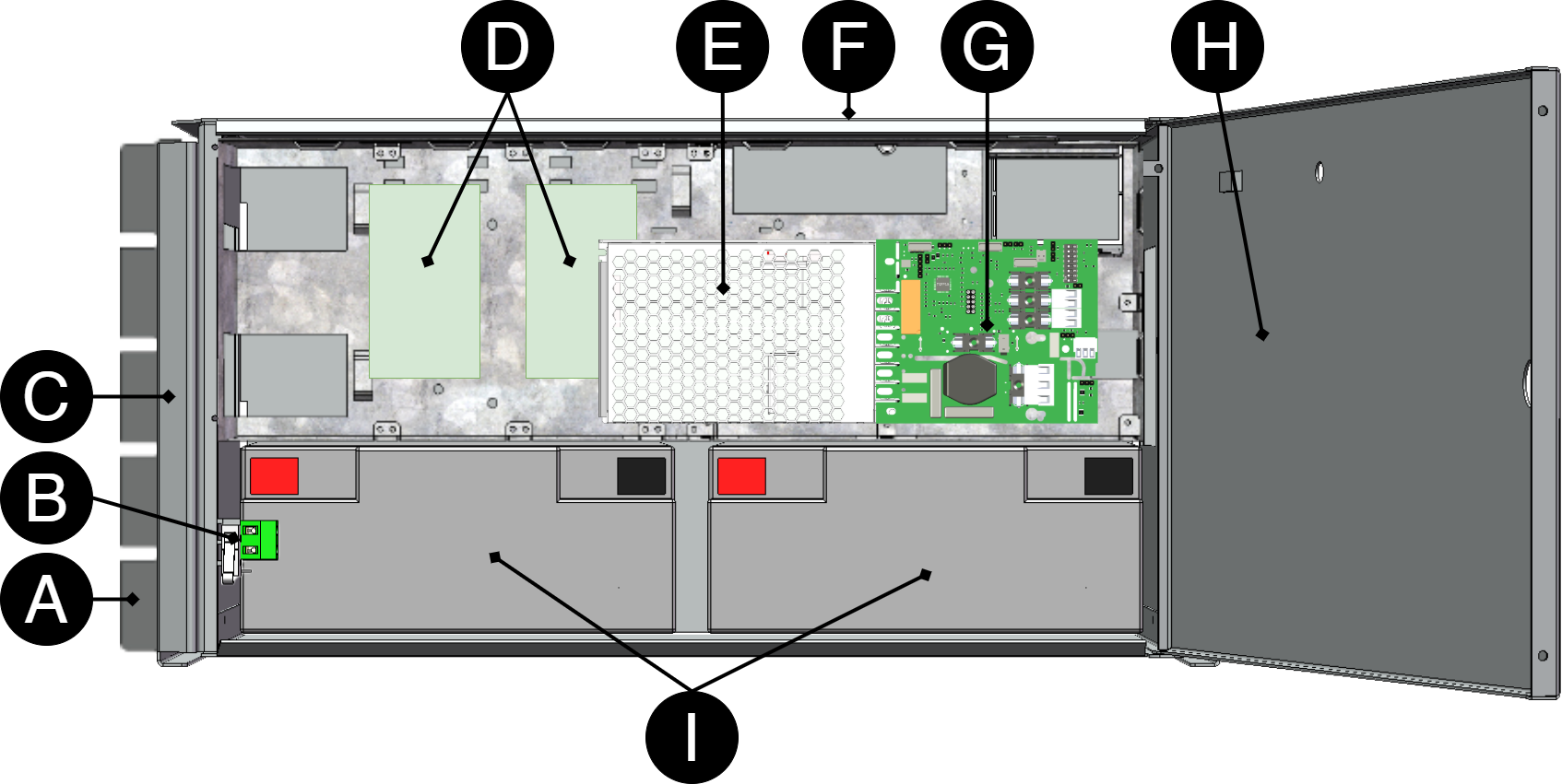
Letter | Explanation |
|---|---|
B1 +, B2 + | Bracket, reversible for wall mounting or 19 "rack. |
B | Optional: Sabotage contact |
C | Cabinet in powder-coated sheet metal. |
D | Optional card slot |
E | Power supply, sits on the back in some configurations. |
F | Cable entries. |
G | Motherboard. |
H | Lockable door. |
I | Space for batteries. |
Batteries - placement and connection
Connecting batteries in FLX M
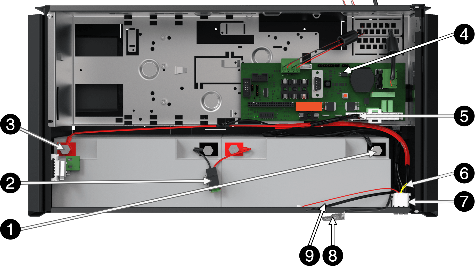
Note that cards (4) differ from different configurations.
No | Explanation |
|---|---|
1 | Minus coil for battery cable from 4. |
2 | Fuse. |
3 | Plus terminal for battery cable from 4. |
4 | Motherboard, varies with configuration. |
5 | Battery cables are located on the system board. |
6 | Yellow cable, which must be cut when connecting the battery box. |
7 | Connection for connection of battery box. |
Connection of batteries in FLX S, FLX M and FLX L
Battery wiring is mounted on the circuit board upon delivery. Pictures below only show how to connect wiring.
Place the batteries in the cabinet with the battery terminals facing outwards.
Connect the battery cable. Red cable on + and black cable on -.
If possible, disconnect mains voltage when replacing the battery.
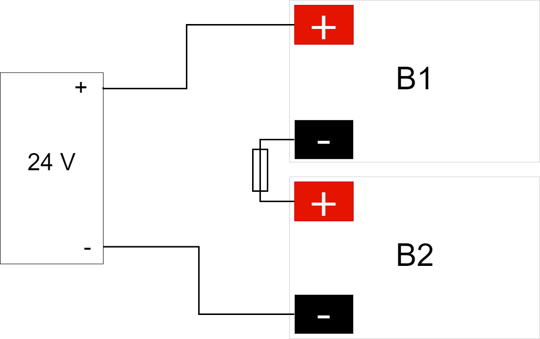
Connect the terminals correctly so that you do not damage the equipment.
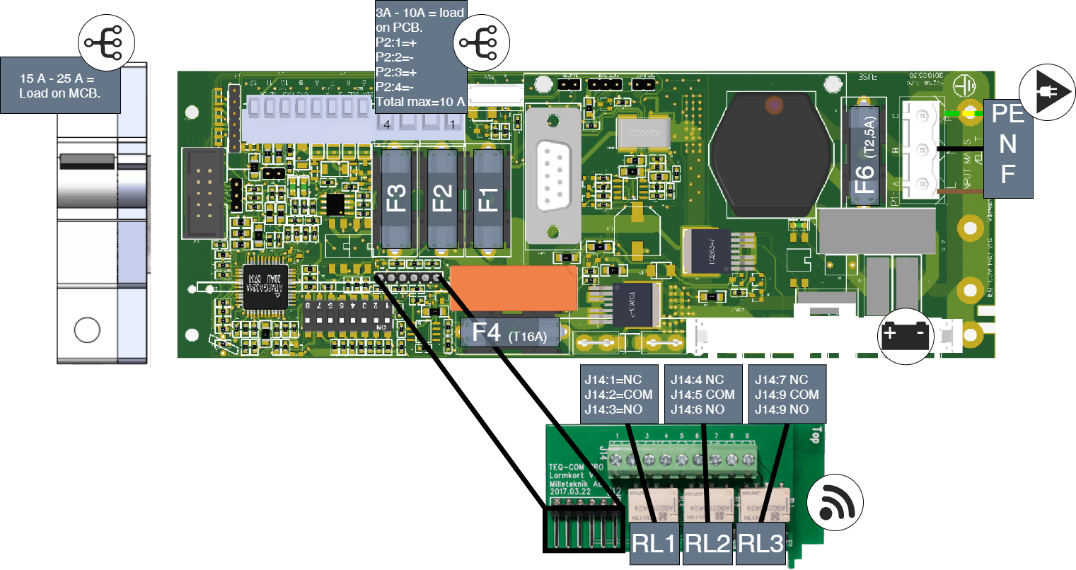
Motherboard - description
Motherboard controls the device, distributes power and communicates with other systems. See technical data for more information.
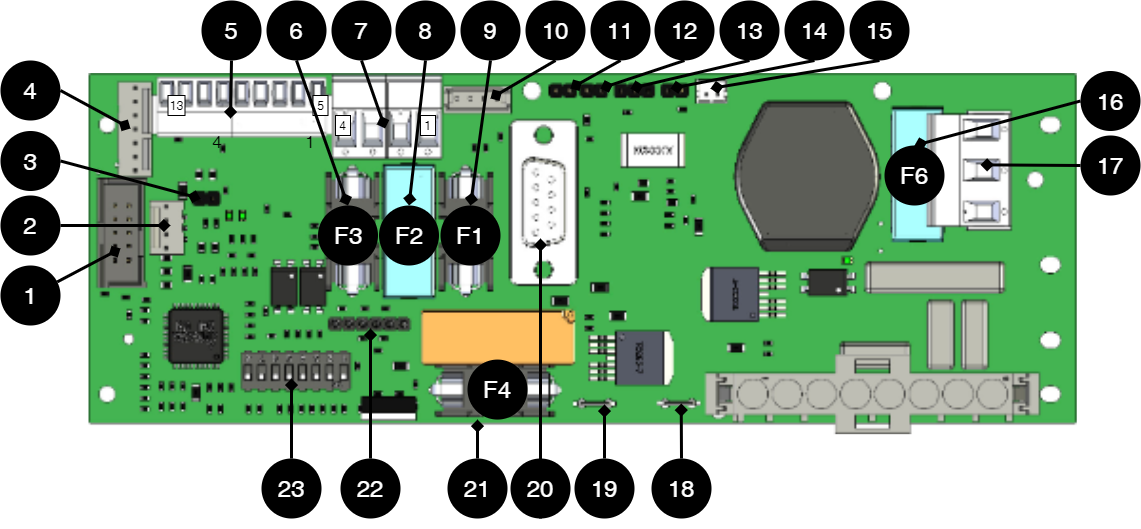
No . | On circuit board | Explanation |
|---|---|---|
1 | PGM1 | Port for firmware update. |
2 | J12 | Connection indicator diode. |
3 | J5 | Termination by jumper, (at over 120 Ω, RS-485). |
4 | J9 | Effect card connection. |
5 | P2:5-13 | Connection for communication. |
6 | F3 | Fuse, load 2 +. (5A and 10A units.) |
7 | P2:1-4 | Load outputs for 5 A and 10 A units only. |
8 | F2 | Fuse, load 1 -. (5A and 10A units.) |
9 | F1 | Fuse, load 1+. (5A and 10A units.) |
10 | J2 | Connection to fan. |
11 | J11 | Tamper switch connection. |
12 | J7 | Connection tamper switch from battery box. |
13 | JU2 | Input from external fuse card, NO. |
14 | J15 | Input from external fuse card, NC. |
15 | J13 | Connection to external alarm. Optional card. |
16 | F6 | See fuses. |
17 | P1:1-3 | Incoming mains, (230 V). Line, Phase, PE. |
18 | J16 | Power resistor connection. |
19 | J4 | Power resistor connection. |
20 | D-sub | Connection option card via D-sub. |
21 | F4 | Battery fuse. |
22 | J8 | Connection to relay/communication card. |
23 | S1 | Dip switch 1-8 |
Fuses
Fuses | Type | Explanation |
|---|---|---|
F1 | See table: fuses | Fuse, load 1 plus +. |
F2 | Fuse, load 1 minus -. | |
F3 | Fuse, load 2 plus +. | |
F4 | Battery fuse. | |
F6 | Mains fuse. |
Warning for replacing fuses (current strength, A)
There is a risk of damage if the fuse is changed to a larger one than what the unit is delivered with. The function of the fuse is to protect the connected load and cables against damage and fire. It is not possible to change the fuse to a larger one to increase the power output.
Fuse | Type |
|---|---|
15 A | T15A |
25 A | T25A |
Mains fuse for 24 V units up to 15 A | T2.5AH250V. Ceramic. |
Mains fuse for 24 v units over to 15 A | T4AH250V. Ceramic. |
Connect the mains to the motherboard (PCB)
Connect mains
Pull wiring through the cable entry on the cabinet.
If possible, secure the mains cable with cable ties where possible.
Important
[sv] Elnätskablage skall hållas åtskilt annat kablage för att undvika EMC-störningar.
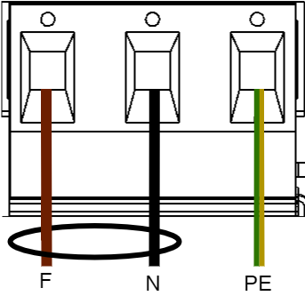
Connect the mains cable to the terminal before it is put back on the motherboard. Secure F and N with cable ties for electrical safety.
Letter | Explanation |
|---|---|
F | Phase |
N | Neutral |
PE | Protective earth |
Electrical mains connection 230 V AC on circuit board
Check that the marking on the circuit board matches the cable arrangement on the terminal block.
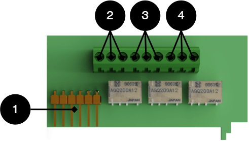
Connect load
Max current
The maximum current must not be exceeded. Max current is indicated on nameplate on the device.
If there are one or more connection cards (to increase the number of load outputs), load must be connected there and not on the main board.
[sv] På kretskort | Explanation |
|---|---|
P2: 1 | Connection for load 1 + |
P2: 2 | Connection for load 1 - |
P2: 3 | Connection for load 2 + |
P2: 4 | Connection for load 2 - |
Connection of load 15 A - 25 A units
For units with a effect card, which is available to handle the higher currents (15 ampere and above), the load must be connected on an optional board.
See documentation for option board for how to connect load.
Warning
Load must not be connected to the motherboard if the device is a 15 A or 25 A, as it will be destroyed during commissioning. Motherboards that are faulty due to incorrect connections are not covered by warranty.
The effect card increases the current for 15 A and 25 A units.
Load cards with blade fuses
The card replaces the load output on the motherboard.
The load card has a different type of fuse that is easier to change and at the same time the card provides a easier connection of the load.
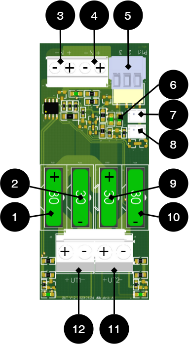 |
No . | On circuit board | Explanation |
|---|---|---|
1, 9 | FUS2, FUS4 | + fuse, 10 A- 25 A depending on the product. |
2, 10 | FUS1, FUS3 | - fuse, 30A. |
3, 4 | IN1, IN2 | Incoming connection 24 V, (from motherboard). |
5 | P1:1-3 | Alarm relay: NC, Com, NO |
6 | D29, D30 | LED. |
7 | J1 | Fuse alarm. |
8 | J2 | Fuse alarm for forwarding to several cards. |
11, 12 | +UT1-, +UT2- | Load connection, outgoing, 24 V |
Load is connected to 11 or 12 on fuse card, see component overview.
Dip-switch - S1
The contact on the dip switch has two positions, ON and OFF.
Dip-switch S1 | Explanation |
|---|---|
1-4 | For address setting to external communication. |
1-2 | Sets time delay for mains failure alarm. (I2C) |
3-4 | Not used. |
5 | Sets the fan speed. |
5-7 | Battery capacity setting. |
8 | For software reset. |
Note
NEO cannot be connected to communication/UC.
Reboot to confirm changes in address, battery and alarm settings to parent system
After the dip-switch has been set for various parameters, the device's software needs to be restarted. This is for the new settings to be stored and take effect.
Important
Rebooting according to this procedure does not interrupt the output voltage.
Restarting the device software is done by turning Dip-switch 8: OFF-ON-OFF (PRO1)
Important
Reboot must be done every time a change is made to the device.
NEO cannot be connected to communication/UC.
Dip-switch - S1
The alarm can be set in time intervals of 0 seconds, 15 minutes, one hour or four hours.
Time | Dip 1 | Dip 2 |
|---|---|---|
0 seconds | OFF | OFF |
15 minutes | ON | OFF |
60 minutes | OFF | ON |
240 minutes | ON | ON |
Note on Dip switch 3
In previous versions of the motherboard, it was possible to use Dip-switch 3 to control whether the unit should alarm for fan failure or not.
This feature has been removed. Alarms for fan faults are given over communication.
Fan speed - setting, Dip-switch 5
Dip-Switch 5 sets the fan speed. (As of software V 4.27.)
Dip-5 | Mode | Temperature limit | Benifit | Drawback |
|---|---|---|---|---|
OFF | Normal mode (factory setting). | High speed above 30°C, restores normal mode when the temperature is 25°C. | Best for battery life. | Louder noise from the fan. |
ON | Office environment mode. | High speed at 35°C, restores normal mode when the temperature is 30°C. | Lower noise level. | Shortens the lifespan of the batteries. |
Battery capacity setting, Dip switch 5-7
The device is set for the battery capacity that the product can handle the most (largest batteries). If other batteries are to be installed, the battery capacity setting needs to be changed so that alarms and functions works as intended.
Setting the new battery capacity is done by keeping the tamper switch pressed while Dip-switch 5-7 is changed and the unit is commissioned.
Open the device and let it operate normally.
Press the tamper switch on the door frame. The device is now in write mode for battery capacity setting.
Set the connected battery capacity on the Dip switch, according to the table.
Release the tamper switch in the door frame. Battery capacity is now stored.
Batteries | Dip 5 | Dip 6 | Dip 7 |
|---|---|---|---|
7,2 Ah | OFF | OFF | OFF |
14 Ah | ON | OFF | OFF |
20 Ah | OFF | ON | OFF |
28 Ah | ON | ON | OFF |
45 Ah | OFF | OFF | ON |
60 Ah | ON | OFF | ON |
90 Ah | OFF | ON | ON |
120 Ah and above | ON | ON | ON |
Resetting data after battery change (Dip-switch 8)
In order for the system to measure the capacity of new batteries, the unit needs to clean up previous battery capacity. Dip-switch 8 makes a software set that, among other things, resets alarms.
Important
The action clears the memory on the card immediately.
Dip-switch 8 must be switched to: OFF-ON-OFF
Connection of PRO 1 with alarm card in NEO
 |
 Connect load (PRO1)
Load is connected to circuit breaker and not to circuit board - see component overview.
To cope with increased power, power is supplied via power cards to circuit breakers. Therefore, loads must be connected to circuit breakers.
Caution
Maximum current must not be exceeded, see plate on the unit.
Alarm card for PRO1
Relay card - description, connections and alarm outputs.
All fault alarm relays must be in the drawn state. Make sure the connection between CO and NC is at closure. Put the measuring instrument on continuity measurement and test closure. This should then indicate a short circuit.
All relay outputs are normally live and give an alarm in the event of no voltage.
 |
No . | Relay (Terminal no.) | The relay is normally energized. | Alarm type or explanation |
|---|---|---|---|
1 | J12 | - | Connection to motherboard. |
2 | J14:1-3 | NC, COM, NC | Power outage alarm. |
3 | J14:4-6 | NC, COM, NO | Alarm for: Fuse failure, tamper switch*, charger failure overvoltage, charger failure undervoltage, cell failure/battery not connected, low battery voltage in case of mains failure and aged battery*. |
4 | J14:7-9 | NO, COM, NC | Alarm for: Low system voltage. |
Via communication on PRO1 card: All alarms and alarms for: Fan fault, overtemperature, subtemperature, short battery life left, overcurrent 100% of minute average, overcurrent 80% daily average and overcurrent 175% second average. * Optional on units that are not certified. | |||
Alarm displayed on cabinet door
In normal mode, the indicator LED shows a solid green light.
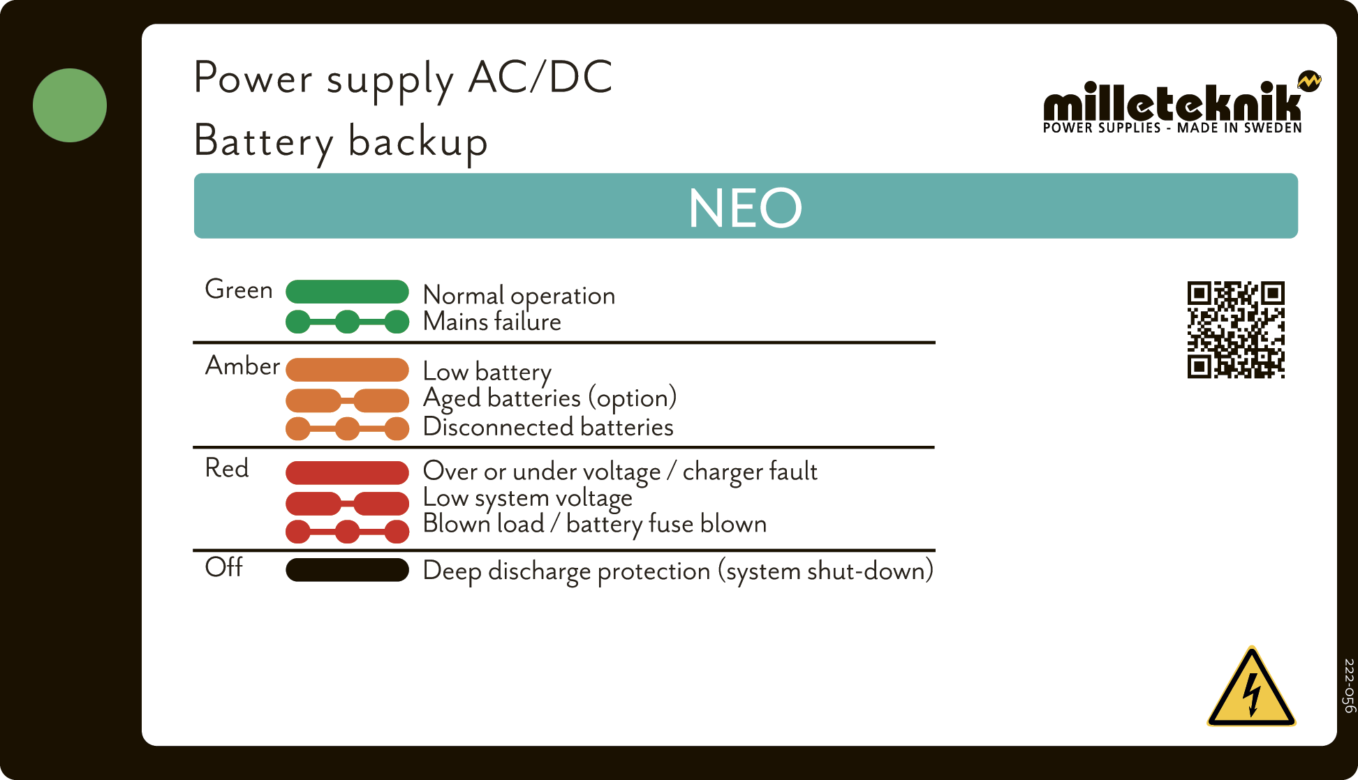 |
The indicator diode (LED) shows | Explanation |
|---|---|
Solid green light | Normal operation. |
Slow green flashes | Not available for NEO. |
Fast green flashes | Mains failure. |
Solid yellow light | Low battery voltage. |
Slow yellow flashes | Aged batteries, (option). |
Rapid yellow flashes | Disconnected batteries / battery cell shortage. |
Solid red light | Overvoltage or undervoltage or charger fault. |
Slow red flashes | Low system voltage. |
Rapid red flashes | Blown load / battery fuse has blown. |
No light / off | Deep discharge protection is activated. (System shutdown). |
When operating system: If the indicator LED is off, deep discharge protection has come into force.
Notice
If the indicator light flashes every 15 seconds, the battery is fully charged and the charge is in rest phase to extend battery life. In the event of a power failure during the rest phase, the battery backup switches to battery operation as usual
Commissioning - how to start the unit
connect load, alarm and possibly. other connections.
Connect batteries
Connect / switch on fuses
Screw the mains cable into the terminal block and attach the terminal block to the motherboard.
Switch on mains voltage.
Connect in this order
To minimize the risk of errors that may occur in connection with a short circuit, connections to the motherboard must be made in this order.
The unit works normally when the indicator LED on the outside of the cabinet door lights up with a solid green light. See front panel for other status indications.
It may take up to 72 hours before the batteries are fully charged.
Circuit boards - Technical data
Technical data, motherboard: PRO 1
Info | Explanation |
|---|---|
Short name: | PRO 1 |
Product description | Main PCB in battery backup with advanced functions and communication to parent system. |
Own consumption, with relay card | Less than 210 mA. 100 mA without power stage with all relays retracted on external alarm card in normal mode. |
Switching time from mains voltage to battery operation | When batteries are idle: <5 microseconds. When batteries are in charge cycle: 0 (none). Batteries rest for 20-day cycles, after which a charging cycle picks up and charges the batteries for 72 hours. If there is a power failure when batteries are in the charge cycle, there is no switching time. |
Incoming electricity network | 230 V AC -240 V AC, 47-63 Hz. |
Fuse on mains | See table: Fuses. |
Indication | Indicator diode on circuit board / cabinet door |
Alarm
Alarm displayed on indicator LED on the front of the cabinet.
Cell fault in battery or unconnected battery.
Charger fault, undervoltage.
Charger fault, overvoltage.
Low system voltage, system voltage below 24.0 V in mains operation.
Low battery voltage, below 24.0 V DC in case of mains failure.
Power failure alarm.
Sabotage switch.
Fuse fault.
Aged battery
Expanding alarm functions are available via communication or with alarm cards.
Info | Explanation |
|---|---|
Alarm on alternating relay? (Yes No) | Yes |
Load outputs, number | 2 |
Voltage at load output | 27.3 V DC |
Voltage limit, upper, on load output | 27.9 V DC |
Voltage limit, lower, on load output. For battery operation and disconnected mains voltage. | 20 V DC |
Priority (always voltage) load outputs (Yes / No) | |
Maximum load, per output | 10 A |
Maximum load, total, (must not be exceeded). | 10 A |
Load output plus (+) secured? (Yes No) | Yes |
Load output minus (-) secured (Yes / No) | Load output 1 = Yes Load passage 2 = No. |
Fuses on output | Yes, see table: Fuses. |
Fuse | Type |
|---|---|
15 A | T15A |
25 A | T25A |
Mains fuse for 24 V units up to 15 A | T2.5AH250V. Ceramic. |
Mains fuse for 24 v units over to 15 A | T4AH250V. Ceramic. |
Electrical protection | |
|---|---|
Deep discharge protection (Yes / No) | Yes. 12 V units protection at 10V, +/- 0.5 V. 24 V units protection at 20, +/- 0.5 V. |
Surge protection (Yes / No) | Yes |
Overtemperature protection (Yes / No) | Yes |
Short circuit protected = (Yes / No) | Yes |
Power supply
Power supply - Technical Data RSP-320-24
In: |
|---|
NEO 24V 15A FLX M |
Info | Explanation |
|---|---|
Output voltage | 27.3 V |
Output current | 0 A - 13.4 A |
Output voltage, ripple | 150 mVp-p |
Overvoltage | 27.6 V - 32.4 V |
Voltage recharge, ripple / current limitation | Less than 1.2 Vp-p |
Efficiency | 89% |
Current limitation | 105% - 135% |
Constant voltage | +/- 0.5% |
Regulatory accuracy | +/- 1.0% |
Input current (230 V) | 2 A |
Mains voltage frequency | 47 Hz- 63 Hz |
Mains voltage | 230 V AC - 240 V AC |
Brand effect | 321.6 W |
Temperature range | -30°C - +70°C |
Humidity range | 20% - 90% RH non-condensed |
Power supply - Technical Data HRP-600-24
In: |
|---|
NEO 24V 25A FLX M |
Info | Explanation |
|---|---|
Output voltage | 27.3 V |
Output current | 0 A - 27 A |
Output voltage, ripple | 150 mVp-p |
Overvoltage | 30 V - 34.8 V |
Voltage recharge, ripple / current limitation | Less than 1.2 Vp-p |
Efficiency | 88% |
Current limitation | 105% - 135% |
Constant voltage | +/- 0.5% |
Regulatory accuracy | +/- 1.0% |
Input current (230 V) | 3,6 A |
Mains voltage frequency | 47 Hz- 63 Hz |
Mains voltage | 230 V AC - 240 V AC |
Brand effect | 648 W |
Temperature range | -30°C - +70°C |
Humidity range | 20% - 90% RH non-condensed |
Technical data enclosures
Enclosures - Technical Data FLX M
Info | Explanation |
|---|---|
Name | FLX M |
Enclosure class | IP 32 |
Measure | Height: 224 mm, width 438 mm, depth 212 mm |
Height units | 5 HE |
Mounting | Wall or 19 "rack |
Ambient temperature | + 5 ° C - + 40 ° C. For best battery life: + 15 ° C to + 25 ° C. |
Environment | Environmental class 1, indoors. 20% ~ 90% relative humidity |
Material | Powder coated sheet |
Color | Black |
Cable entries, number | 4 |
Batteries that fit | 2 pieces 12 V, 20 Ah. |
Fan | Yes |
Batteries - recommended, not included
Batteries are not included they are sold separately
Batteries are sold separately.
45 Ah, 12 V AGM battery
Fits in | Number of batteries |
|---|
Battery type | V | Ah |
|---|---|---|
Maintenance-free AGM, lead-acid battery. | 12 V | 45 Ah |
Article number | E-number | Article name | Terminal | Measure. Height width depth | Weight per piece | Make |
|---|---|---|---|---|---|---|
MT113-12V45-01 | 5230546 | UPLUS 12V 45Ah 10+ Design Life battery | M5 Bult | 197x165x170 mm | 14.5 kg | UPLUS |
Reserve operating times for different alarm classes - overview
The table shows the requirements for backup operating time and recharging of batteries for different alarm classes.
Important
This is a guide and all times are approximate and may differ from actual times. Load, temperature and other factors come into play, which is why exact time can not be provided.
Applies to new batteries.
Amperage and batteries vary with configuration, check if the configuration can handle batteries and amperage.
Medium current | 7.2 Ah | 14 Ah | 28 Ah | 45 Ah |
|---|---|---|---|---|
Loading | Backup operating time (approx.), Minutes | |||
0.5 A | 450 | 820 | 1650 | 2350 |
1 A | 260 | 485 | 970 | 1460 |
2 A | 150 | 280 | 560 | 920 |
4 A | 90 | 165 | 335 | 550 |
6 A | 67 | 125 | 245 | 405 |
8 A | 57 | 105 | 210 | 350 |
10 A | 44 | 80 | 160 | 270 |
12 A | 38 | 70 | 140 | 235 |
14 A | 33 | 60 | 120 | 200 |
16 A | 28 | 50 | 100 | 170 |
18 A | 25 | 45 | 89 | 150 |
20 A | 23 | 42 | 84 | 142 |
Medium current | 28 Ah | 42 Ah | 65 Ah | 70 Ah |
|---|---|---|---|---|
- | 4 batteries (14 Ah) | 6 batteries (14 Ah) | 4 batteries (20Ah + 45 Ah) | 10 batteries (7 Ah) |
Loading | Backup operating time (approx.), Minutes | |||
0.5 A | 1650 | 2090 | 5574 | 3440 |
1 A | 970 | 865 | 3252 | 2118 |
2 A | 560 | 815 | 1770 | 1329 |
4 A | 335 | 490 | 930 | 864 |
6 A | 245 | 360 | 600 | 605 |
8 A | 210 | 310 | 426 | 544 |
10 A | 160 | 240 | 342 | 414 |
12 A | 140 | 210 | 270 | 363 |
14 A | 120 | 180 | 234 | 311 |
16 A | 100 | 150 | 204 | 286 |
18 A | 90 | 130 | 150 | 254 |
20 A | 84 | 126 | 138 | 241 |
Medium current | 90 Ah | 110 Ah | 135 Ah | 155 Ah |
|---|---|---|---|---|
- | 4 batteries (45 Ah) | 6 batteries (20 Ah + 45 Ah) | 6 batteries (45 Ah) | 8 batteries (20 Ah + 45 Ah) |
Loading | Backup operating time (approx.), Minutes | |||
0.5 A | 4705 | 5796 | 7056 | 8215 |
1 A | 2928 | 3582 | 4392 | 5070 |
2 A | 1836 | 2247 | 2754 | 3230 |
4 A | 1183 | 1438 | 1762 | 2018 |
6 A | 788 | 959 | 1175 | 1345 |
8 A | 748 | 861 | 1048 | 1150 |
10 A | 570 | 689 | 839 | 920 |
12 A | 499 | 603 | 699 | 765 |
14 A | 427 | 516 | 629 | 655 |
16 A | 404 | 499 | 592 | 590 |
18 A | 359 | 444 | 526 | 520 |
20 A | 340 | 420 | 498 | 495 |
Medium current | 180 Ah | 200 Ah | 225 Ah |
|---|---|---|---|
- | 8 batteries (45 Ah) | 10 batteries (20 Ah + 45 Ah) | 10 batteries (45 Ah) |
Loading | Backup operating time (approx.), Minutes | ||
0.5 A | 9408 | 12972 | 11760 |
1 A | 5856 | 7872 | 7320 |
2 A | 3672 | 4548 | 4590 |
4 A | 2365 | 2670 | 2945 |
6 A | 1577 | 1780 | 1960 |
8 A | 1500 | 1558 | 1800 |
10 A | 1140 | 1246 | 1410 |
12 A | 950 | 1038 | 1200 |
14 A | 855 | 890 | 1055 |
16 A | 810 | 902 | 995 |
18 A | 715 | 802 | 885 |
20 A | 680 | 722 | 840 |
Subject to typos.
Regulations and certifications
Requirements that the product meets
EMC: | EMC Directive 2014 / 30EU |
Electricity: | Low voltage directive: 2014/35 / EU EN 62368-1 |
CE: | CE directive according to: 765/2008 |
Emission: | EN61000-6-: 2001 EN55022: 1998: -A1: 2000, A2: 2003 Klass B, EN61000-3-2: 2001 |
Immunity: | EN61000-6-2:2005, EN61000-4-2, -3, 4, -5, -6, -11 SS-EN 50 130-4:2011 Edition 2, EN50131-6 |
Emission | EN55032 (CISPR32) Class B |
Environment | REACH Regulation: Directive 1907/2006, WEEE Regulation: Directive 20021961E, RoHS Regulation: Directive 2015/863 |
Note
The product is part of electrical systems, is subject to the relevant electrical and safety directives and is not a machine according to the Machinery Directive (2006/42/EC).


Address and contact details
Milleteknik AB |
Ögärdesvägen 8 B |
S-433 30 Partille |
+46 31 340 02 30 |
www.milleteknik.com |