
EN54-4 Certified / SBF110:8 Approved battery backup
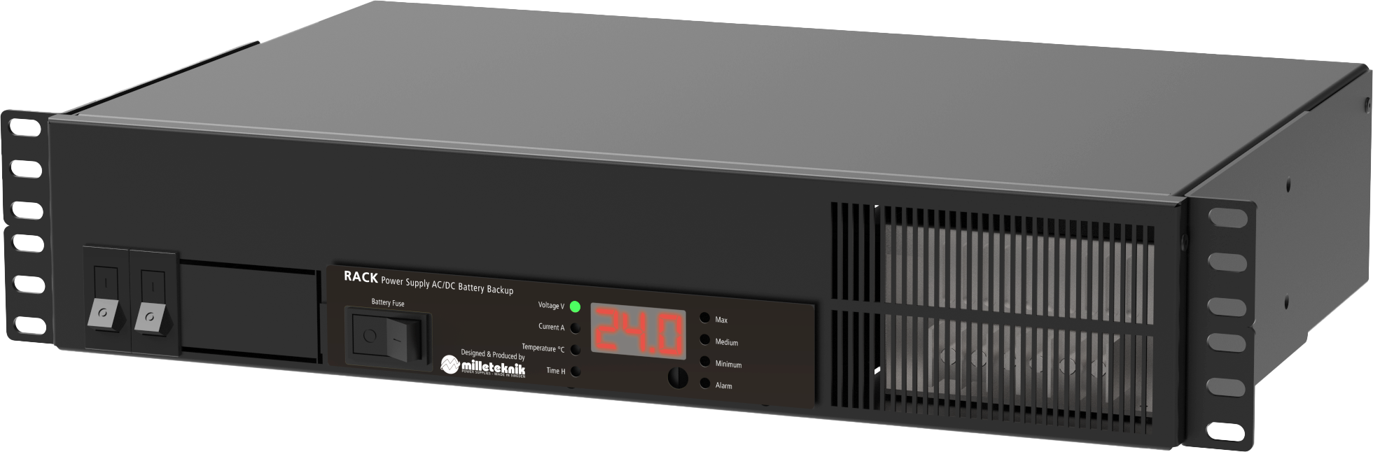
The unit is mounted in a 19" rack.
Product Identification
Product designation | Part number | E-number (SE) |
|---|---|---|
EN54 48V 13A 2U | 2U01R10048P130-EN54 | 52 135 58 |
Revisions and the edition of this document
The current and most recently published edition of this document is available at www.milleteknik.com.
The validity of this document can not be guaranteed, as new editions are published without prior notice.
Original instructions for use: Swedish.[1].
Instructions for use, technical data and translations thereof may contain errors. It is always the responsibility of the installer to install the product in a safe manner.
Symbols
Symbols | Name | Explanation |
|---|---|---|
 | Warning | Risk of electric shock, improper installation or hot surfaces. Appears in some manuals |
 | Note | Used for supplementary information that clarifies the text. |
 | Caution/Important | Indicates the risk of equipment damage or malfunction. Also used for information that is important but not security-related |
 | Tips | Displays practical advice or shortcuts for installation, operation, or service. |
 | CE marking | The product complies with applicable EU directives and harmonised standards. |
 | Read the manual | Please read manual before installation and service. |
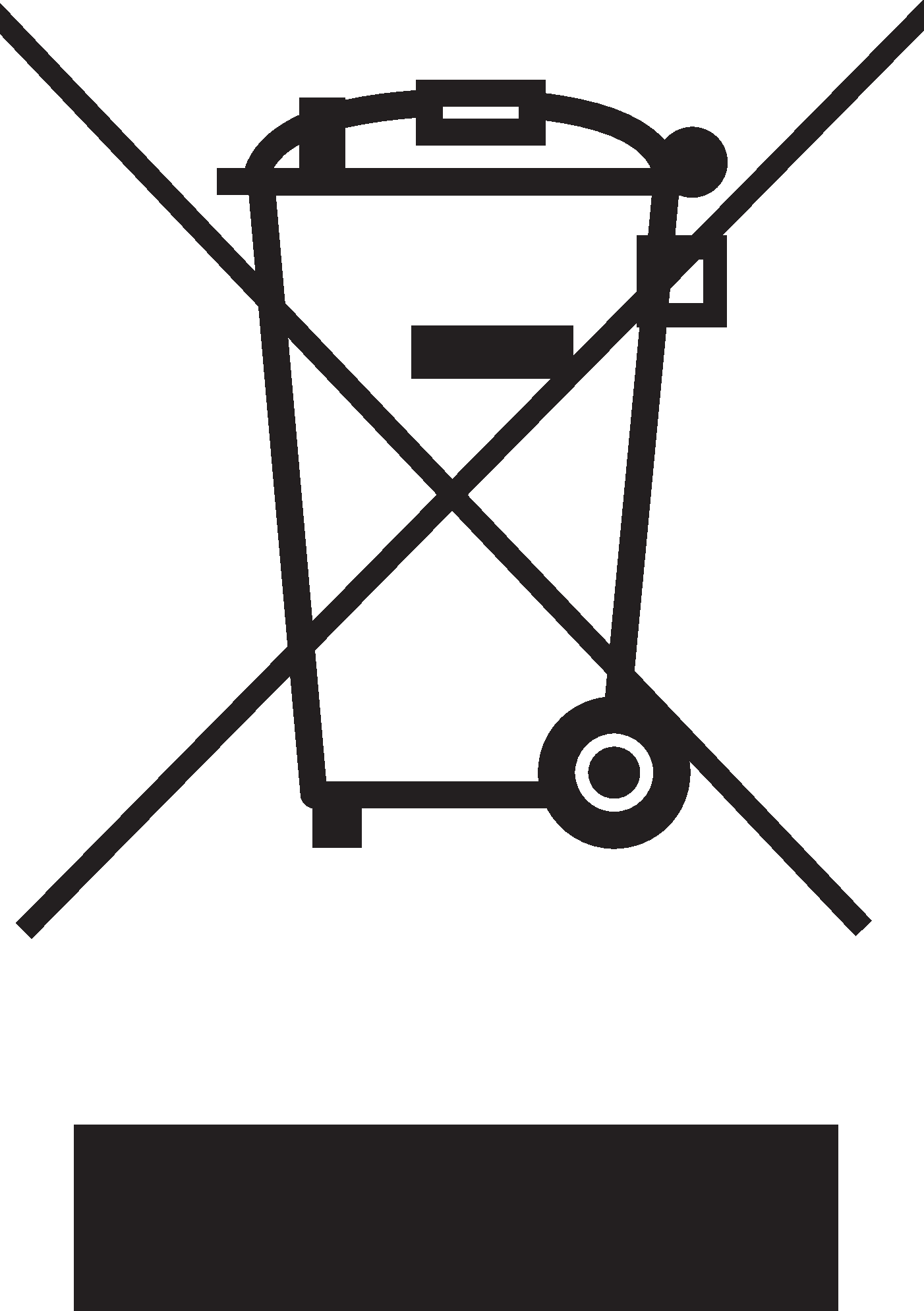 | Do not dispose of in household waste | The product is covered by the WEEE Directive and must not be disposed of with household waste, it must be recycled and delivered to a recycling centre. |
 | Recycling | Packaging, products and other materials that do not contain electronics must be recycled in accordance with local environmental regulations. |
Installation and commissioning
Instructions for installation and commissioning.
Installation video

Read this first!
If possible, leave 100 mm of free space.
The system is intended for use in a controlled indoor environment.
Only authorized persons should install and maintain the system.
It is the installer's responsibility to ensure that the system is suitable for its intended use.
Documents accompanying the system must be kept in or in its immediate vicinity.
Ventilation should not be covered. Mains voltage should be disconnected during installation.
All information subject to change.
Upon installation of this product, the installer acknowledges and accepts the limitations of this product as described in this manual.
Instructions original language: Swedish.
About translation of this document
User manual and other documents are in the original language in Swedish. Other languages may be machine translated and/or not reviewed, errors may occur.
Component overviews
Component overview
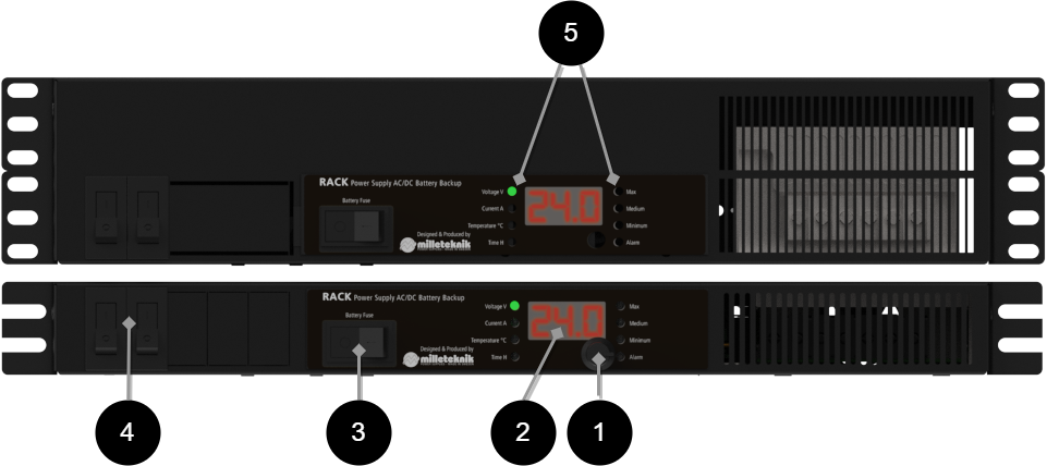
Letter | Explanation |
|---|---|
1 | Motherboard. |
2 | Lockable door. |
3 | Battery fuse |
4 | Load fuses |
5 | LED |
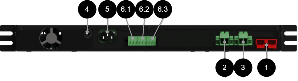
No . | Explanation | Comment |
|---|---|---|
1 | Connection of battery cables | - |
2 | Load output 2 | The fuse on the front is the one closest to the display. |
3 | Load output 1 | Fuse on the front is the one closest to the corner. |
4 | Temperature sensor | - |
5 | Mains connection | 230 V. |
6.1 | Relay 1 | Mains failure, NO/CO/NC. |
6.1 | Relay 2 | PSU over/under voltage, aged battery, battery not connected, broken fuse, low battery voltage in battery operation, NO/CO/NC. |
6.3 | Relay 3 | Low system voltage, NO/CO/NC. |
Enclosures
General assembly instructions
Installation in 19" rack
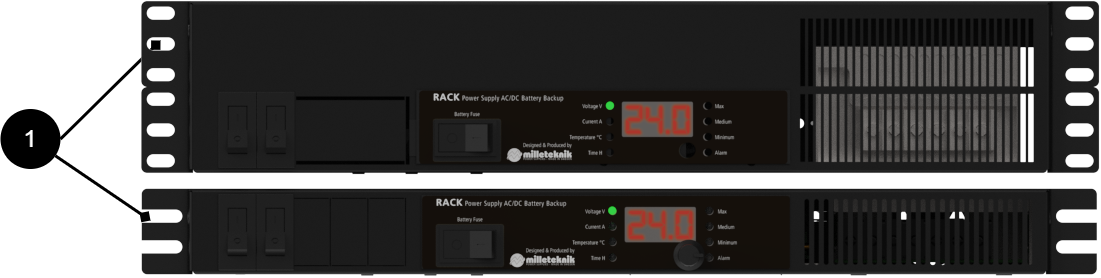
No . | Explanation |
|---|---|
1 | The unit is mounted with screws into a 19" rack. |
Note
Installation of the RACK EN54-COVER can be done before or after the unit is installed.
Installation of battery shelf
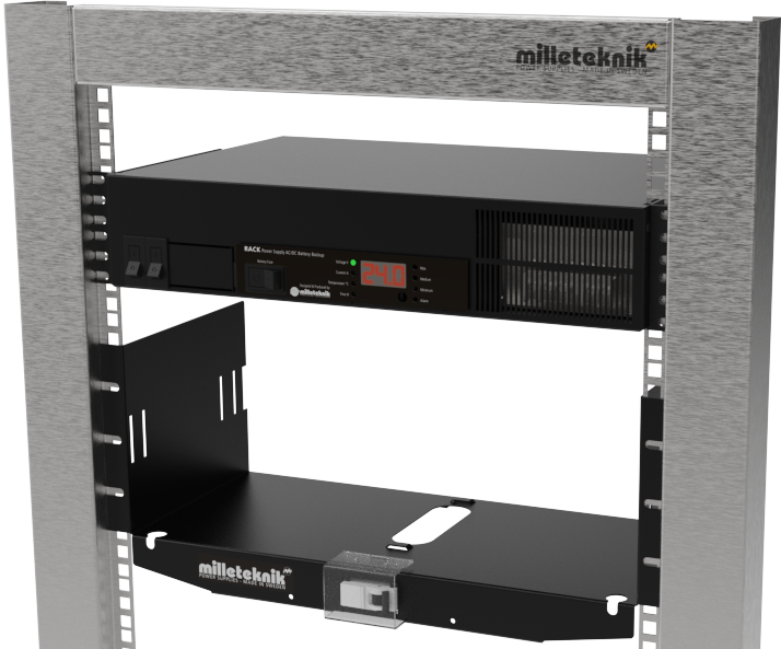
The battery shelf must be mounted in a 19" rack. Use the appropriate screw for the rack to attach the shelf.
Attach the shelf in at least two places on each side. Use as many screws as you need to keep the batteries and the shelf secure and stable.
In order for the device to function, batteries must be connected. These must be placed on a battery shelf that comes with prepared cabling. The battery shelf must be mounted in the rack before batteries are placed.
Warning
The unit must be installed in a locked and protected indoor environment.
Risk of access to battery terminals. terminal protection must cover battery poles.
Connect mains
Pull wiring through the cable entry on the cabinet.
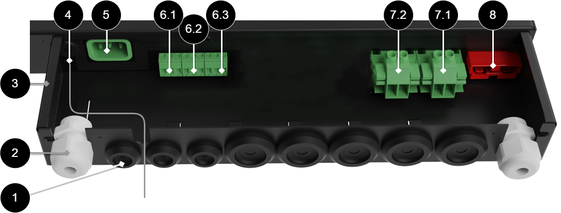
No | Explanation |
|---|---|
1 | Cable entries for alarm cables and load cables. |
2 | Strain relief for mains cable. |
3 | Shelter in powder-coated sheet metal. |
4 | Temperature sensor. |
5 | Connection for mains cable. |
6.1-6.3 | Relay 1-3, see component overview. |
7.2 | Load output 2. |
7.1 | Load output 1. |
8 | Forklift glove for connecting battery cables. |
Important
To protect the outputs on the back, a protective housing (1) in sheet metal is included. If the facility is to be EN 54-4 or SBF 110:8 approved, the protective housing must be mounted.
Connect mains 230 V AC
Connection of 230 V mains cabling to the unit takes place through the device connector on the back of the unit. Connect the power supply to the mains via easily accessible isolation switch and suitable ground fault protection (which is part of the building's existing wiring).
Temperature sensor
Temperature sensor for measuring battery temperature, place sensor between batteries.
The device has an internal temperature sensor and an external temperature sensor to measure internal and ambient temperature.
Alarm
See table 6.1-6.3
Alarm cable for battery fuse monitoring
Alarm cable for battery fuse monitoring.
Communication - optional
Connection to communication (via RS-485) can take place during customer customization.
Maximum wire resistance
The voltage at the furthest load point must not be lower than the requirements of the connected load.
Lowest voltage is given when batteries are almost discharged (21 V / 42 V) together with voltage drop in wiring. Ensure that the load can handle the lowest voltage with voltage drop in cabling.
Facts about ILAST
ILAST is the sum of the connected loads. The cable resistance (RKABEL) is the sum of the cable resistance in both conductors x the cable length.
Minimum load voltage in battery operation taking into account voltage drop in cables = VUT(MIN) - (ILAST x RKABEL). VUT(MIN) is the limit for deep discharge (21 V / 42 V) when the batteries are empty.
The table takes into account to and from conductors, i.e. the actual distance in meters must be used.
RKABEL | Ω / m |
|---|---|
1.5 mm2 | 0.024 Ω / m |
2.5 mm2 | 0.014 Ω / m |
4 mm2 | 0.009 Ω / m |
6 mm2 | 0.006 Ω / m |
10 mm2 | 0.0035 Ω / m |
16 mm2 | 0.0022 Ω / m |
Connection of batteries in battery shelf
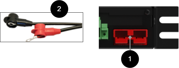
Use the included cabling to connect the batteries. Be careful not to short the terminals of the batteries. First connect wiring in batteries, (2). Cabling must have rubber pole protection that covers the battery pole. Then connect battery connector to the battery backup, (1).
Set battery capacity
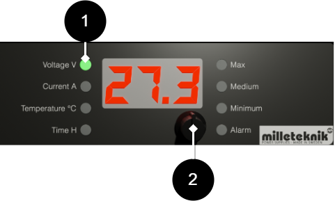
No | Explanation |
|---|---|
1 | Set the steering wheel so that V lights up green. |
2 | Press and hold the multi selector for three seconds until C00 appears on the display. Turn the multi-selection dial until C01 is displayed and press the multi-selection dial (a light push) to select the battery capacity. To accept the setting, press and hold the button for three seconds. |
Factory default setting is 2 x 20 Ah.
Turn to C00 and press the button once to return to the regular menu.
Note
The device retains settings even if power is completely cut to the device. You therefore do not need to set the battery capacity again when changing the battery.
How to start the device
After connection, start must take place in the following steps:
Connection/voltage setting of battery part.
Voltage setting to mains.
Apply voltage to the load by switching on the circuit breaker.
Commissioning
When all connections have been made, the system has been configured and the three steps for how to start the device have been completed - then the following should happen:
Status indication is off in normal operation.
The load will be powered. Check with a voltmeter that the load voltage is between 26 and 27.3 V DC (48 V, 52-54.6 V DC).
The batteries must be charged. Check this by measuring across the battery terminals. (Depending on the condition of the batteries, the voltage may vary but should be above 24 V DC, (48 V DC) and slowly increase by approximately 0.001 V/10 sec. When fully charged, the voltage of the batteries should be 27.3 V DC (48 V, 54, 6 V DC).
The ALARM indicator diode on the panel must be off.
All fault alarm relays must be in the pulled state. Check that there is a connection between CO and NC. Set the measuring instrument to continuity measurement and test termination. This should then indicate a short circuit.
All relay outputs are normally energized and thus give an alarm in de-energized mode. When connecting to communication, the parent system sends queries. The superior system must then give an alarm if, for example, the unit is de-energized.
Communication - optional
Connection to communication (via RS-485) can take place during customer customization.
List of settings via multi-selector wheel
Configuration mode on the display, accessed by a long button press on the multi-selector wheel.
(J) value is adjustable
(N) value is resettable
(U) Can perform a test/function
On display | Explanation |
|---|---|
C00 | Return to normal viewing mode. |
C01 | Setting of battery capacity in Ah (J). |
C02 | Setting the minimum allowed battery operating time (J). |
C03 | Alarm limit for low battery voltage in battery operation (J). |
C04 | Delay alarm mains failure (J). |
C05 | Low system voltage alarm (J). |
C06 | Show relay status, 100s = Power supply, 10s = Batteries 1s = Mains interruption. Tripped relay shows for power supply = 011. Tripped relay for battery shows = 101. Tripped relay for mains failure = 110. Example if all relays are set = 000. Alarm=0, energized relay=1. |
C07 | Charge Cycle (J). Duration of the charging phase, 72 hours. Full rest phase cycle is 20 days. |
C08 | Highest measured tension (N). |
C09 | Lowest measured tension (N). |
C10 | Highest measured temperature (N) - external temperature sensor. |
C11 | Lowest measured temperature (N) - external temperature sensor. |
C12 | Number of minutes with overtemperature (N). |
C13 | Number of minutes with sub-temperature (N). |
C14 | Stopwatch load current above 170% of nominal load (N). Risk of load bills triggering. |
C15 | Minute counter load current above 100% of nominal load (N). Risk that dimensioning requirements are not met. |
C16 | Day counter load current above 80% of nominal load (N). Risk that the warranty period is not reached. |
C17 | Perform battery connection test (U). |
C18 | Perform Cell Test (U). |
C19 | Perform Weekly Test (U). |
C20 | Calibrate battery voltage (J). Factory setting - May not be changed. |
C21 | Calibrate voltage from mains plug (J). Factory setting - May not be changed |
C22 | Calibrate zero current (N). Factory setting - May not be changed |
C23 | Calibrate load current (J). Factory setting - May not be changed |
C24 | Setting of nominal load (J). |
C25 | Limit value for deep discharge protection (J). ATTENTION! 1HE has hardware-controlled deep discharge. |
C26 | Limit value for weekly test (J). |
C27 | Original value for Cell test (J). |
C28 | Allowed additional voltage drop during cell test (J). |
C29 | Raw data from the A/D converter. |
C30 | Raw data from the A/D converter. |
C31 | Raw data from the A/D converter. |
C32 | Raw data from the A/D converter. |
C33 | Raw data from the A/D converter. |
C34 | Raw data from the A/D converter. |
C35 | Raw data from the A/D converter. |
C36 | Internal flags. |
C37 | Internal flags. |
C58 | Measured value from internal temperature sensor. |
C59 | Highest measured value from internal temperature sensor. |
Maintenance
The system with the exception of batteries is maintenance-free when installed in an indoor environment.
Maintenance schedule batteries
The maintenance schedule applies to batteries made by UPLUS and with the following serial names: US, USL, USF, and for batteries made by XLENT POWER with serial names XLT and XLL. For maintenance instructions see separate document "care instructions valve-regulated lead-acid battery”.
Series designation | Battery type | Replace battery after |
|---|---|---|
XLT | 3-5 years | 2-3 years |
US | 6-9 years | 3-5 years |
USL | 10-12 years | 5-7 years |
USF | 12 years | 8-10 years |
* battery life depends mainly on ambient temperature and charging current. An AGM battery should never be charged with more than 30% of its rated capacity. The battery will be fully charges, but the charning current must not excced 30% of its rated capacity. | ||
Charging voltage from power supply | 12 V units | 24 V units | 48 V units |
|---|---|---|---|
Minimum charging voltage | 13.6 V | 27.2 V | 54.4 V |
Maximum charging voltage | 13.7 V | 27.4 V | 54.8 V |
Tolerance | +/- 0.5% | +/- 0.5% | +/- 0.5% |
terminal voltage | After 15 minutes of rest / charging. |
|---|---|
Minimum terminal voltage | 12.9 V |
Maximum allowable difference between battery pairs | 0.5 V |
New battery with terminal voltage below 12.0 V is defective and should be reported to the supplier. | |
Temperature in battery backup | Temperature |
|---|---|
Lowest | 15 ° C |
Recommended | 20 ° C - 25 ° C |
Highest | 32 ° C |
Warranty is valid only if the temperature is within these levels. | |
Installation control batteries
Check that the battery is completely clean and that the terminals are free from corrosion.
Check and note the temperature in the battery compartment.
Check the terminal voltage of each battery before installation. If the difference between the batteries exceeds 0.5 V, the battery loop should be equalized in connection with installation. If any battery has a terminal voltage of less than 12V, this battery must be replaced with a new battery and reported to the supplier.
Connect the battery and check the charging voltage. The charging voltage should be between 2.25 V - 2.27 V per cell = between 13.5 V - 13.62 V for a 12 V system and between 27.0 V - 27.24 V for a 24 V system.
Year-round inspection
Check that the battery is completely clean and that the terminals are free from corrosion. If there is corrosion on the terminals: Check that the battery does not leak acid. Then clean the terminals and reconnect the battery. Then lubricate with battery terminal grease over the connected terminal.
Check and note the temperature in the battery compartment.
Check and note the average current.
Check that all connections are securely fastened and that there is no gap in the connection.
Check that the fan (if units have a fan) is working properly. Clean the fan if necessary.
Check the charging voltage by measuring with a multimeter between the connection points + & amp; -. The charging voltage should be between 2.25-2.27 volts per cell = between 13.5-13.62V for a 12V system and between 27-27.24V for a 24V system.
Turn off the rectifier and let the batteries rest for 10 - 15 minutes. Then measure the terminal voltage of each battery. After resting, the terminal voltage must be between 12.9 V - 13.5 V.
Product sheet - power supply / battery backup
Product Sheet
EN54-4 Certified / SBF110:8 Approved battery backup
The unit is mounted in a 19" rack.
Product Identification
Product designation | Part number | E-number (SE) |
|---|---|---|
EN54 48V 13A 2U | 2U01R10048P130-EN54 | 52 135 58 |
Technical description
EN54 power supplies fire alarms with 48 V DC or 24 V DC. The rectifier in the power supply converts 230 V AC down to 48 V DC or 24 V DC and powers all important parts of the fire alarm system. EN54 power supply is certified for use in safety installations that must comply with EN54-4 and/or be approved for SBF 110:8.
Batteries, for example, drive the access system further when the power grid goes down.
Areas of application
Areas of application | Yes | No |
|---|---|---|
Fire alarm | ✔ | |
EN54-4 approved fire alarm systems. | ✔ | |
SBF 110:8, SBSC approved fire alarm system. | ✔ | |
PowerWatch compatible | ✔ |
Electrical data
Electrical data | |||||||||||||||||||||||||||||||||||||||||||||||||
|---|---|---|---|---|---|---|---|---|---|---|---|---|---|---|---|---|---|---|---|---|---|---|---|---|---|---|---|---|---|---|---|---|---|---|---|---|---|---|---|---|---|---|---|---|---|---|---|---|---|
Supply voltage | 230V AC, +/- 10%, 47Hz- 63Hz | ||||||||||||||||||||||||||||||||||||||||||||||||
Charge current | Depending on the power outlet. | ||||||||||||||||||||||||||||||||||||||||||||||||
Efficiency[a] | 89% | ||||||||||||||||||||||||||||||||||||||||||||||||
Standby consumption | 10.1 W | ||||||||||||||||||||||||||||||||||||||||||||||||
Voltage out | 54.6 V DC, (48 V DC) Also applicable in battery operation. | ||||||||||||||||||||||||||||||||||||||||||||||||
Current (A)[b] | 13A | ||||||||||||||||||||||||||||||||||||||||||||||||
[a] At rated load. [b] Power outlet/load is specified as max, normal current output should be 80% of max. | |||||||||||||||||||||||||||||||||||||||||||||||||
Fuses | |
|---|---|
Mains fuse | 4 A 250V AC, ceramic, 5 x 2 0mm |
Load fuses | 15A |
Battery fuse |
|
Circuit Boards | Internal power consumption (during battery operation) | Additional information |
|---|---|---|
1 HE 48 V | 200 mA |
Load outputs
Alarm and protection
Alarms | Yes | No |
|---|---|---|
Power outage alarm, 10 sec delay | ✔ | |
Power Outage Alarm | ✔ | |
Summing alarm, temperature failure (above/below limit value), fuse failure: load fuse triggered, battery fuse triggered, fuse in external board with load outputs, ground fault (D-Sub), signal failure (D-Sub), failure or missing temperature sensor (internal or external) and fan failure. | ✔ | |
System failure | ✔ |
Protection | Yes | No | |||||||||||||||||||||||||||||||||||||||||||||||
|---|---|---|---|---|---|---|---|---|---|---|---|---|---|---|---|---|---|---|---|---|---|---|---|---|---|---|---|---|---|---|---|---|---|---|---|---|---|---|---|---|---|---|---|---|---|---|---|---|---|
Battery charge protection/controlled charging[a] |
| ||||||||||||||||||||||||||||||||||||||||||||||||
Battery fault monitoring | ✔ | ||||||||||||||||||||||||||||||||||||||||||||||||
✔ | |||||||||||||||||||||||||||||||||||||||||||||||||
Fuse protection | ✔ | ||||||||||||||||||||||||||||||||||||||||||||||||
Overload Protection/Surge Protection | ✔ | ||||||||||||||||||||||||||||||||||||||||||||||||
Over-temperature protection | ✔ | ||||||||||||||||||||||||||||||||||||||||||||||||
Power Supply Failure Monitoring | ✔ | ||||||||||||||||||||||||||||||||||||||||||||||||
Short circuit protection | ✔ | ||||||||||||||||||||||||||||||||||||||||||||||||
System monitoring/self-test | ✔ | ||||||||||||||||||||||||||||||||||||||||||||||||
Undervoltage protection/low system voltage | ✔ | ||||||||||||||||||||||||||||||||||||||||||||||||
[a] Controlled charging protects and extends battery life. [b] When the deep discharge protection is activated, the device turns off and the LED goes out. | |||||||||||||||||||||||||||||||||||||||||||||||||
Communication and Indications
Communication and Indications | Yes | No | Additional information. | ||||||||||||||||||||||||||||||||||||||||||||||
|---|---|---|---|---|---|---|---|---|---|---|---|---|---|---|---|---|---|---|---|---|---|---|---|---|---|---|---|---|---|---|---|---|---|---|---|---|---|---|---|---|---|---|---|---|---|---|---|---|---|
Communication to the parent system | ✔[a] | ||||||||||||||||||||||||||||||||||||||||||||||||
Alarm to subcentral | ✔ | ||||||||||||||||||||||||||||||||||||||||||||||||
PowerWatch compatible[b] | ✔ | ||||||||||||||||||||||||||||||||||||||||||||||||
Indications | ✔ | LED displays information and alarms on circuit boards and on the outside of the housing. LED on the housing | |||||||||||||||||||||||||||||||||||||||||||||||
[a] Applies to communication against the parent system, active only if configuration allows. [b] PowerWatch consists of a cable and software, it is ordered separately. See Appendix. | |||||||||||||||||||||||||||||||||||||||||||||||||

The PowerWatch is available as an option for the product.
Interfaces | Mode of communication | Protocols | |
|---|---|---|---|
RS-485 | Differential signaling | OSDP | |
Battery
Enclosure and Mechanics
Enclosure and Mechanics | |
|---|---|
Type |
|
IP class | |
Material | Powder Coated Sheet |
Colour |
|
Height units | |
Cable grommets | 8 pcs |
Knockout hole | 1 pc. on the back |
Fan in enclosure | ✔✘ |
Assembly, installation and qualification requirements
Mounting | Yes | No |
|---|---|---|
19" rack. | ✔ | |
Wall. | ✔ |
Installation | Yes | No |
|---|---|---|
Fixed installation. | ✔ |
Dimensions, weight and packaging information
Net weight | Weight with packaging |
|---|---|
8 kg | 8.3 kg |
Packaging | |
|---|---|
Packaging | Cardboard and impact protection in cardboard |
Quantity in pack | 1 pc. |
Packaging Type (GS1 T0137) | BX box. |
Conditions EUR pallet | EUR pallets may not be stacked during transport or storage. Stacking may result in damage to product and packaging |
Transport environment | The product must be protected from condensation and direct precipitation during transportation. |
Transport temperature (without battery) | −30 °C to +70 °C |
Storage environment | Dry indoor environment, protected from condensation. Relative humidity: max 95%, non-condensing |
Storage temperature without batteries | −20 °C to +60 °C |
Contact
So when you reach us | |
|---|---|
Switchboard | 031-340 02 30 |
Technical support | support@milleteknik.se |
Sales | sales@milleteknik.se |
WWW | www.milleteknik.se |
Address | Ögärdesvägen 8B, 433 30 Partille |
About this information
Specifications are subject to change without notice. Milleteknik accepts no liability for typographical errors. Information is updated without prior notice. Milleteknik with the associated logo is a trademark of Milleteknik AB. PowerWatch is a trademark of Milleteknik AB. |
Publication date 2026-09-15
Compliance and regulatory compliance
Delivery time, warranty and terms
Delivery time, warranty and terms | |||||||||||||||||||||||||||||||||||||||||||||||||
|---|---|---|---|---|---|---|---|---|---|---|---|---|---|---|---|---|---|---|---|---|---|---|---|---|---|---|---|---|---|---|---|---|---|---|---|---|---|---|---|---|---|---|---|---|---|---|---|---|---|
Warranty period[a] | The product has a five (5) year warranty against manufacturing defects. | ||||||||||||||||||||||||||||||||||||||||||||||||
Special warranty conditions | The battery backup should be used in conjunction with UPLUS 10+ Design Life batteries. The fan should be cleaned annually and replaced if necessary. The average load shall not exceed 80% of the rated capacity of the power supply. Ambient temperature shall not exceed 32°C. Batteries and wear parts are not covered by warranty. See also general terms and conditions. | ||||||||||||||||||||||||||||||||||||||||||||||||
General Terms and Conditions | ALEM09 with exceptions, see: www.milleteknik.se/conditions/ | ||||||||||||||||||||||||||||||||||||||||||||||||
Support | Telephone support and email support during the warranty period are free of charge. For spare parts that are not covered by warranty, there is a charge | ||||||||||||||||||||||||||||||||||||||||||||||||
Delivery and stock | |||||||||||||||||||||||||||||||||||||||||||||||||
Delivery time[b] | 5 working days. Or as per agreement. Delivery from factory, transportation time is added. | ||||||||||||||||||||||||||||||||||||||||||||||||
[a] If the device is purchased through a wholesaler or other supplier, other warranty conditions may apply. [b] In the case of larger orders, delivery time increases, acc. to agreement. | |||||||||||||||||||||||||||||||||||||||||||||||||
Operation and maintenance
Operation | Data | Additional information | |||||||||||||||||||||||||||||||||||||||||||||||
|---|---|---|---|---|---|---|---|---|---|---|---|---|---|---|---|---|---|---|---|---|---|---|---|---|---|---|---|---|---|---|---|---|---|---|---|---|---|---|---|---|---|---|---|---|---|---|---|---|---|
Environment | Indoor, environmental class 1. | ||||||||||||||||||||||||||||||||||||||||||||||||
Operating temperature (recommended) | +15°C to +25°C | For the best battery life. Higher temperatures significantly shorten the life of the batteries. | |||||||||||||||||||||||||||||||||||||||||||||||
Operating temperature (permissible)[a] | +5°C to +40°C | Class 1 according to EN 50131-6/ EN 60839-11 | |||||||||||||||||||||||||||||||||||||||||||||||
Load, power supply | 80% | Average load shall not exceed 80% of the rated capacity of the power supply. | |||||||||||||||||||||||||||||||||||||||||||||||
Ventilation, free distance around the enclosure. | 100 mm | Ventilation openings must not be blocked or covered. | |||||||||||||||||||||||||||||||||||||||||||||||
Ventilation, in front and behind the enclosure. | 100 mm | Ventilation openings must not be blocked or covered. | |||||||||||||||||||||||||||||||||||||||||||||||
[a] Specifies the permissible ambient temperature range in which the product can operate without damage. See also table on battery life. | |||||||||||||||||||||||||||||||||||||||||||||||||
Yes | No | Interval | Additional information |
|---|---|---|---|
✔ | Annually | Battery terminal voltage must be measured. Check that the average load does not exceed 80% of the rated capacity of the power supply. Fan should be checked and replaced after 5—8 years | |
✔ | The product is maintenance-free |
Certifications and approvals
Complies with | Directives |
|---|---|
Emissions | EN61000-6-:2001 EN 55022:1998: -A 1:2000, A 2:2003 Class B, EN61000-3-2:2001, EN 55032 (replaces EN 55022)A11:2020 (CISPR 32), Class B |
Immunity | |
CE | CE marking according to Regulation (EC) No 765/2008 |
RoHS | RoHS Directive 2011/65/EU, including amendment (EU) 2015/863 |
EMC | EMC Directive 2014/30/EU |
Electrical safety (LVD) | Low Voltage Directive 2014/35/EU |
Approved according to standard | Yes | No |
|---|---|---|
EN50131-6 | ✔ | |
EN 54-4:1997, EN 54-4:1997 /AC:1999, EN 54-4:1997 /A1:2002 and EN 54-4:1997 /A2:2006. | ✔ |
Complies with | Yes | No |
|---|---|---|
SBF 110:8 | ✔ |

Certificate number, report number | Designation in test report |
|---|---|
6P07698-2 | - |
How do certificates apply if optional is installed in the device?
EN54-4 clarification
External connection: Certification for EN 54-4 is not affected by accessories or equipment that are mounted outside the unit and then connected to its input/outputs.
Internal Mounting: In devices certified according to EN 54-4, no options may be physically mounted inside the enclosure if certificates are to be valid.
Optional Requirements: Please note that all options used with certified products must be manufactured by Milleteknik. Options from other manufacturers are not allowed
Environmental data
Environmental data | Y/N | Information | Additional information. | ||||||||||||||||||||||||||||||||||||||||||||||
|---|---|---|---|---|---|---|---|---|---|---|---|---|---|---|---|---|---|---|---|---|---|---|---|---|---|---|---|---|---|---|---|---|---|---|---|---|---|---|---|---|---|---|---|---|---|---|---|---|---|
Building Product Declaration (BPD) | ✔ | Yes, see iBvd at www.milleteknik.se. | - | ||||||||||||||||||||||||||||||||||||||||||||||
REACH Information Obligation (EC) No 1907/2006 | ✔ | Yes, see the DoC at www.milleteknik.se The product complies with REACH Regulation (EC) No 1907/2006. | If empty, the product is not covered. | ||||||||||||||||||||||||||||||||||||||||||||||
SVHC substances, CAS/EC | ✔ | Yes, lead, 7439-92-1/231-100-4 | For text, see iBvd at www.milleteknik.se. If blank, substance is missing. | ||||||||||||||||||||||||||||||||||||||||||||||
Subject to the RoHS Directive, (EU) 2015/863) | ✔ | Yes, see the DoC at www.milleteknik.se | |||||||||||||||||||||||||||||||||||||||||||||||
WEEE 2012/19/EU | ✔ | The product contains electrical components or wiring and is covered by the WEEE Directive (2012/19/EU). | If empty, the product is not covered. End-of-life products must be returned to a recycling centre | ||||||||||||||||||||||||||||||||||||||||||||||
Battery Regulation (EU) 2023/1542 | If empty, the product is not covered. | ||||||||||||||||||||||||||||||||||||||||||||||||
SCIP No 2008/98/EC | ✔ | Yes, registered under the EU Waste Directive where applicable, (2008/98/EC). | If empty, no SCIP number is needed. | ||||||||||||||||||||||||||||||||||||||||||||||
Conflict minerals (EU) 2017/821 | ✗/✗/✗/✗/✔ | No=Gold, Tungsten, Tantalum, Cobalt. Yes=Tin | Tin in solders in printed circuit boards purchased through a Swedish supplier. | ||||||||||||||||||||||||||||||||||||||||||||||
Contains nanomaterials: EC 1272/2008 | ✗ | The product does not contain nanomaterials. | |||||||||||||||||||||||||||||||||||||||||||||||
Ecodesign 2009/125/EC | Milleteknik's products are intended for professional use and are therefore not directly covered by the Ecodesign Regulation (EU 2019/1782). As some components may be covered, we nevertheless disclose relevant information[a], where applicable, to provide our customers with confidence in their choice. | ||||||||||||||||||||||||||||||||||||||||||||||||
Machine Directive 2006/42/EC | The product is part of electrical systems, is subject to the relevant electrical and safety directives and is not a machine according to the Machinery Directive (2006/42/EC). Will be replaced by Machinery Regulation (EU) 2023/1230, which will apply in 2027. | ||||||||||||||||||||||||||||||||||||||||||||||||
The product is designed and constructed for a long service life, which reduces the environmental impact. The life of the product (except wearing parts) depends on, among other things, environmental factors, mainly ambient temperature, unforeseen load on components such as lightning strikes, external impact, handling errors, etc. Products are recycled, simply because they are modular, by being left at the nearest recycling station or sent back to the manufacturer.[b]Contact your distributor for more information. | |||||||||||||||||||||||||||||||||||||||||||||||||
[a] Standby consumption and power. [b] Costs incurred in connection with recycling are not reimbursed. | |||||||||||||||||||||||||||||||||||||||||||||||||
Manufacturer and country of origin
Manufacturer[a] | Milleteknik AB | ||||||||||||||||||||||||||||||||||||||||||||||||
Customs tariff number | 85044095[b] | ||||||||||||||||||||||||||||||||||||||||||||||||
Country of origin | Sweden | ||||||||||||||||||||||||||||||||||||||||||||||||
[a] Manufacturer refers to the brand indicated on the product. In the event of a discrepancy between the marking of the product and this product sheet, the marking of the product shall apply [b] Verify with the Customs Ombud/Customs Service for export/import; alternative classification 85044055 may become applicable if the product is assessed as a battery charger. | |||||||||||||||||||||||||||||||||||||||||||||||||
Appendix
Backup operating time on batteries
The reserve operating time in battery operation depends on how large a load is connected to the power supply. If the load varies, as with frequent opening of door locks, the time that batteries can continue to power the security system decreases. To get an estimate of reserve operating times see: www.milleteknik.se/Manualer/FaQ/Reservdrifttider/
About certifications and options
How do certificates apply if optional is installed in the device?
Battery backups from Milleteknik can be divided into three categories:
Devices that are not third-party certified to use burglar alarm or fire alarm systems.
Devices that are third-party certified for use in burglar alarm systems (SSF 110:8).
Devices certified for use in fire alarm systems (EN54).
How do certificates apply if optional Milleteknik is fitted in the device?
Product Series | Marking | Regulatory framework | |||||||||||||||||||||||||||||||||||||||||||||||
|---|---|---|---|---|---|---|---|---|---|---|---|---|---|---|---|---|---|---|---|---|---|---|---|---|---|---|---|---|---|---|---|---|---|---|---|---|---|---|---|---|---|---|---|---|---|---|---|---|---|
ECO, NEO, PoE, Options and accessories. | No certification marking | - | |||||||||||||||||||||||||||||||||||||||||||||||
NOVA[a] |  | SSF 1014, Issue 6, Alarm Class 4 | |||||||||||||||||||||||||||||||||||||||||||||||
EN54[b] | | EN 54-4:1997 /AC:1999 and EN 54-4:1997 /A2:2006. | |||||||||||||||||||||||||||||||||||||||||||||||
Batteries | No certification marking | SSF 1014, Issue 6, Alarm Class 4 EN 54-4:1997 /AC:1999 and EN 54-4:1997 /A2:2006. | |||||||||||||||||||||||||||||||||||||||||||||||
[a] The unit meets the requirements for installation in facilities that must be SSF 1014 approved. SSF 1014 certificate is only valid when certified together with the parent system. For SSF 1014 certificate to be valid, only one (1) load exit may [b] The MX series is EN54 certified in the EU country. Certifkat is not published on SBSC | |||||||||||||||||||||||||||||||||||||||||||||||||
How do certificates apply if optional is installed in the device?
EN54-4 clarification
External connection: Certification for EN 54-4 is not affected by accessories or equipment that are mounted outside the unit and then connected to its input/outputs.
Internal Mounting: In devices certified according to EN 54-4, no options may be physically mounted inside the enclosure if certificates are to be valid.
Optional Requirements: Please note that all options used with certified products must be manufactured by Milleteknik. Options from other manufacturers are not allowed
PowerWatch
Product designation | Item No. | E-number (SE) |
|---|---|---|
PowerWatch | A-OT0000UPG02P2V3P3 | 52 137 06 |
Alarms that can be set in PowerWatch |
|---|
Charger failure, overvoltage |
Charger failure, undervoltage |
Fan failure, (in case of externally connected fan) |
Fuse failure on load |
Low battery voltage, in battery operation |
Power outage, delay 10 seconds |
Unconnected battery |
Unit not calibrated |
Eligibility requirements, installation
Eligibility requirements vary between countries. The table summarizes national requirements for fixed installation and connection of equipment with a plug socket, respectively.
Options on the secondary side of the product, such as 12 V, 24 V or 48 V DC, are connected according to the respective instructions. Work on the network connection of the product shall be carried out in accordance with national qualification requirements
Permission Requirements for Installation | Fixed installation (230 V) | Plug | Additional information |
|---|---|---|---|
Sweden | ✔ | ✗ | Fixed installation may be performed by technicians but shall be under the responsibility of a qualified installer. (Electrical Safety Act, SS 436 40 00) Plug may be connected without authorization. |
Norway | ✔ | ✔ | Requirements for qualified electricians also for equipment with a plug socket in fixed installations. (NEK 400, DSB |
Finland | ✔ | ✗ | Plug may be connected without authorization. (Tukes, SFS 6000 |
Denmark | ✔ | ✗ | Plug may be connected without authorization. (Safety Board |
Germany | ✔ | ✗ | All fixed installations require a qualified electrician according to VDE 0100. Plug sockets may be connected without authorization, but only by person with basic electrical knowledge (“Elektrotechnisch unterwiesene Person”) |
Reference table: environmental classes according to EN 50130-5 (referred to in EN 50131-6)
Class | Type | Temperature range |
|---|---|---|
Environmental Class 1 | Heated indoors (type office/residence). | +5°C to +40°C |
Environmental Class 2 | Generally indoors (type warehouses/stairwells, not temperature controlled). | -10°C to +40°C |
Environmental class 3 | Protected outdoors. | -25°C to +50°C |
Environmental class 4 | Generally outdoors. | -25°C to +60°C |
Reference table: manufacturer's stated service life and recommended battery replacement
Battery Type (Design Life)[a] | Battery replacement time in normal operation, +20°C. | Replacement during hot operation, +30°C | Replacement during hot operation, +40°C | ||||||||||||||||||||||||||||||||||||||||||||||
|---|---|---|---|---|---|---|---|---|---|---|---|---|---|---|---|---|---|---|---|---|---|---|---|---|---|---|---|---|---|---|---|---|---|---|---|---|---|---|---|---|---|---|---|---|---|---|---|---|---|
3 - 5 years | 2 - 3 years | 1 - 1.5 years | 0.5 - 0.75 years | ||||||||||||||||||||||||||||||||||||||||||||||
6 - 9 years | 5 - 6 years | 2.5 - 3 years | 1.2 - 1.5 years | ||||||||||||||||||||||||||||||||||||||||||||||
10 - 12 years | 6 - 7 years | 3 - 3.5 years | 1.5 - 1.75 years | ||||||||||||||||||||||||||||||||||||||||||||||
15 + years | 10 - 12 years | 5 - 6 years | 2.5 - 3 years | ||||||||||||||||||||||||||||||||||||||||||||||
[a] Valid in case of completely unused battery stored under optimal conditions. | |||||||||||||||||||||||||||||||||||||||||||||||||
About this information
Specifications are subject to change without notice. Milleteknik accepts no liability for typographical errors. Information is updated without prior notice. Milleteknik with the associated logo is a trademark of Milleteknik AB. PowerWatch is a trademark of Milleteknik AB. |
Publication date 2026-09-15
Appendix: Mount EN-54 Cover
EN54-COVER for rack-mounted EN54 is mandatory for installation in facilities that are EN 54-4 or SBF 110:8 approved.
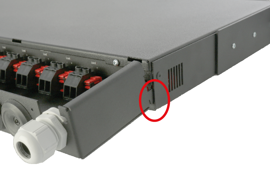
1. Slide the hooks into the RACK EN54 COVER on the back of the unit.
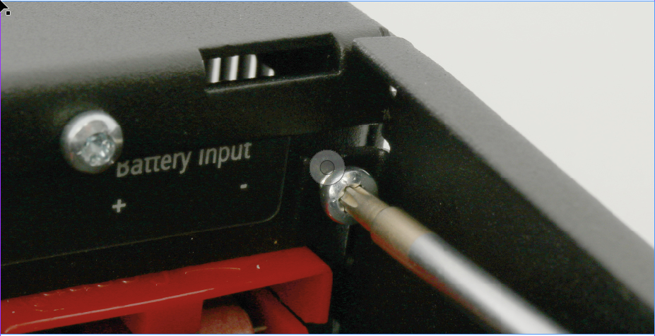
2. Screw on the EN54-COVER, (2 screws).
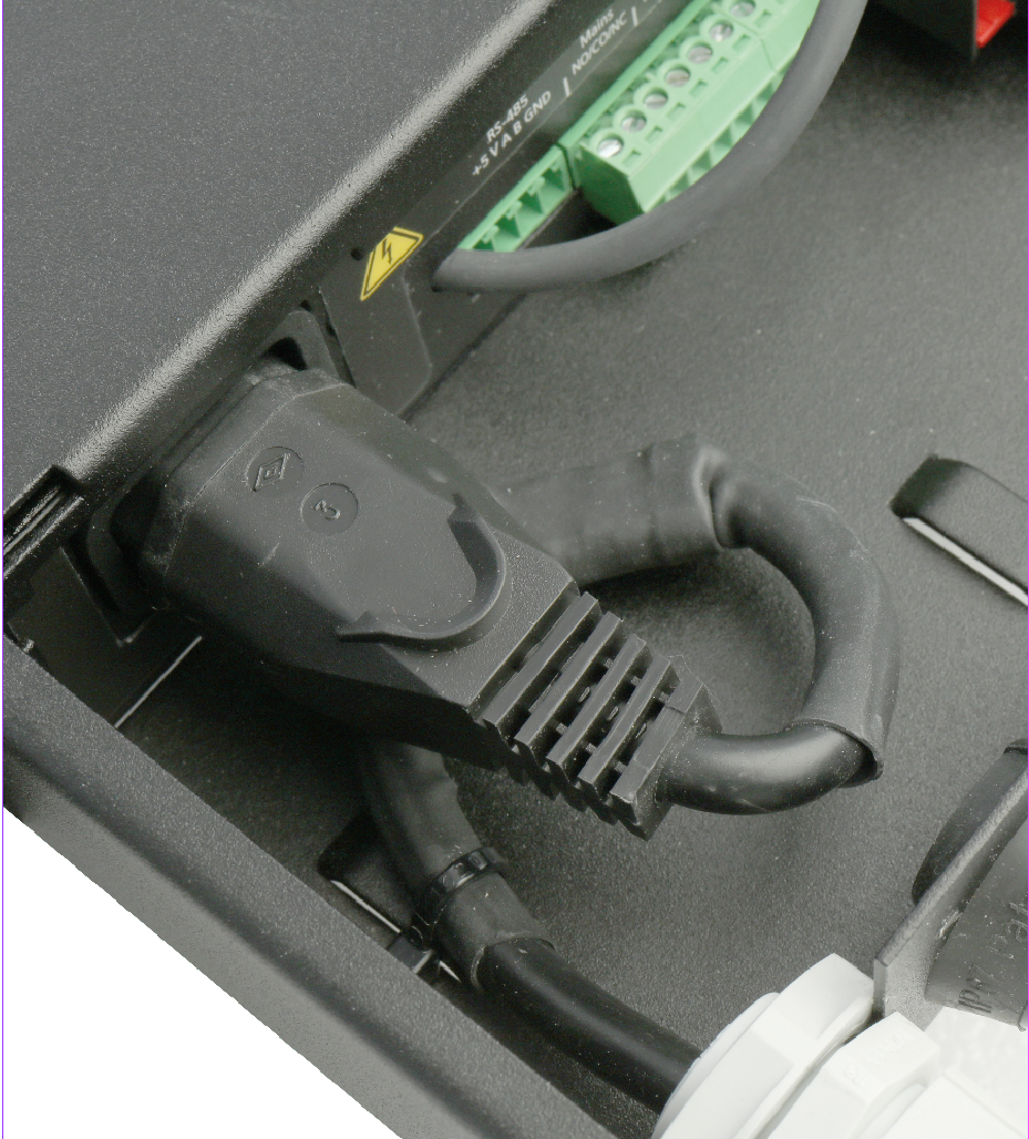
Connect other cabling before connecting to the mains. Note: The mains cable must be positioned as in the picture. The temperature sensor's protective sleeve may need to be removed to get the temperature sensor through the cable entry.
Important
All connecting cables must go through the cable glands.

4. Push the hooks into the RACK EN54-COVER cover on the back of the RACK unit.
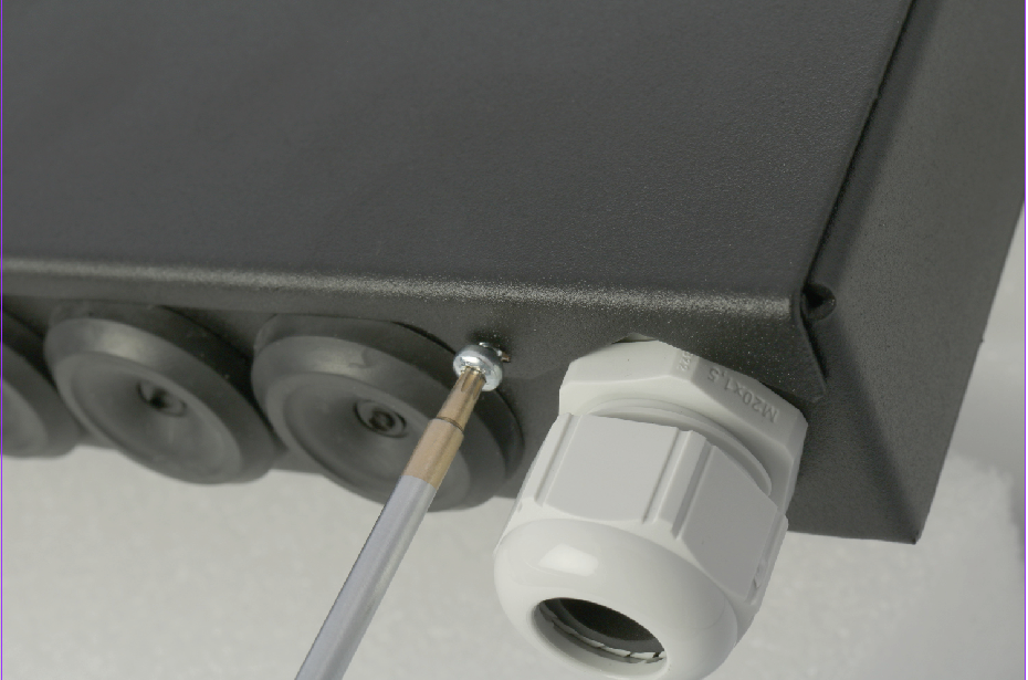
5. Screw on the cover, (2 screws).
[1] Translations in languages other than Swedish are indicative only and not verified. Translation should always be checked against the Swedish original to ensure accurate information