Installation and commissioning
Instructions for installation and commissioning.
Product Identification
Product designation | Article number | E-number (SE) |
|---|---|---|
ECO 24V 5A 2HE | 2U02C10424P050 | 52 137 89 |
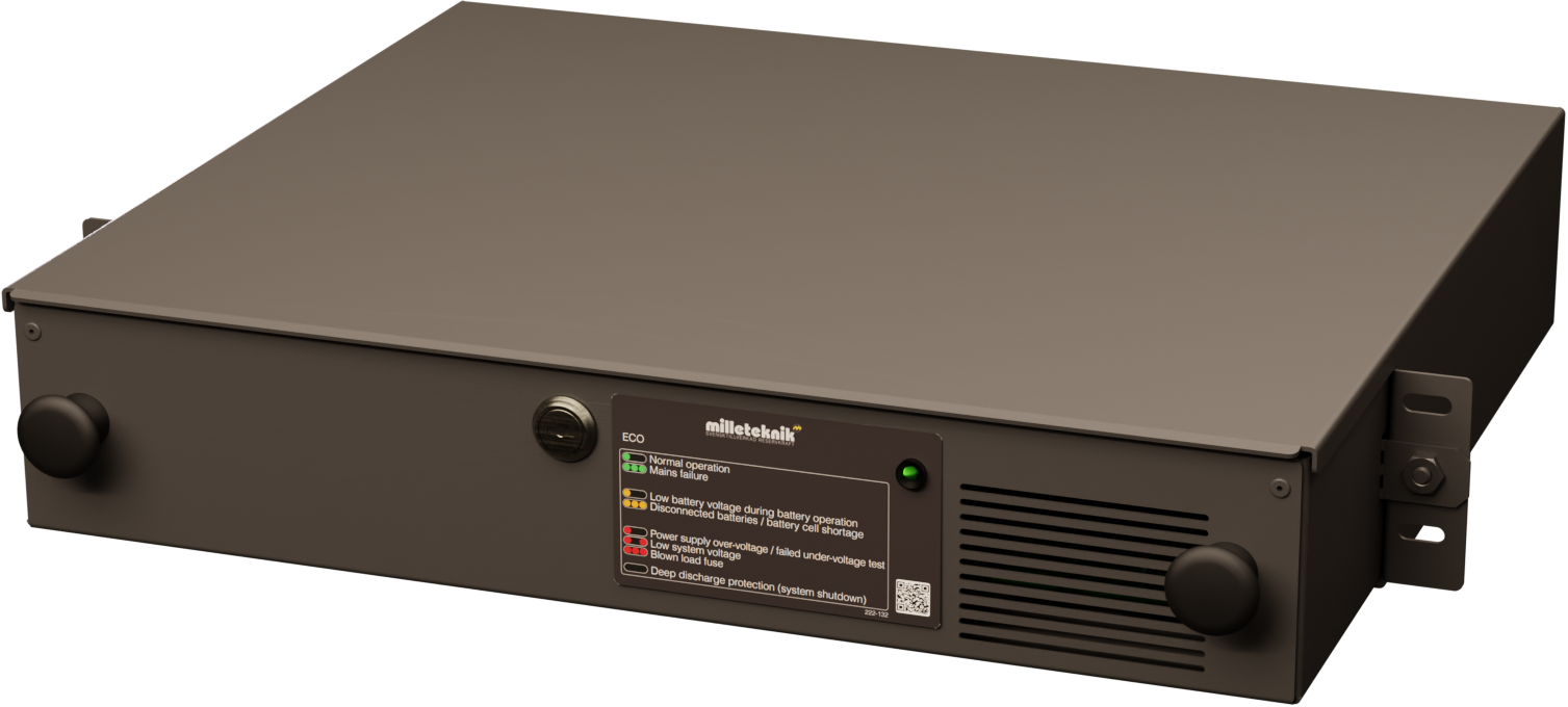
ECO power supply with battery backup
Technical description
Compact rack-mounted battery backup in 2 HE with 24 V, 5A and space for 2 × 12 V 20 Ah batteries, optimized for mounting in 19" racks.
Revisions and the edition of this document
The current and most recently published edition of this document is available at www.milleteknik.com.
The validity of this document can not be guaranteed, as new editions are published without prior notice.
Original instructions for use: Swedish.[1].
Instructions for use, technical data and translations thereof may contain errors. It is always the responsibility of the installer to install the product in a safe manner.
Symbols
Symbols | Name | Explanation |
|---|---|---|
 | Warning | Risk of electric shock, improper installation or hot surfaces. Appears in some manuals |
 | Note | Used for supplementary information that clarifies the text. |
 | Caution/Important | Indicates the risk of equipment damage or malfunction. Also used for information that is important but not security-related |
 | Tips | Displays practical advice or shortcuts for installation, operation, or service. |
 | CE marking | The product complies with applicable EU directives and harmonised standards. |
 | Read the manual | Please read manual before installation and service. |
 | Do not dispose of in household waste | The product is covered by the WEEE Directive and must not be disposed of with household waste, it must be recycled and delivered to a recycling centre. |
 | Recycling | Packaging, products and other materials that do not contain electronics must be recycled in accordance with local environmental regulations. |
Installation shall be carried out by a competent electrician in accordance with the applicable national electrical installation rules.
The product is of protection class I and must be connected to a grounded 230 V AC circuit.
A main switch according to IEC 60947-1 shall be provided in the fixed installation. The switch should be easily accessible and clearly marked with its function.
The area of the supply cable shall be at least 1,0 mm² and fitted with a fuse T 2,5 A (slow-blown) or equivalent.
AC and low voltage cables must not be pulled together. Keep separate cable chutes or bundles
Check that protective earth (PE) is properly connected before turning on voltage.
Ensure free air circulation around the enclosure at least 100 mm, unless otherwise specified. Ventilation openings must not be covered.
The product is intended for indoor installation in normal environment (pollution number 2 and indoor class 1).
These general requirements apply to all Milleteknik products with 230 V mains connection.
Enclosures
General assembly instructions
Indoor mounting in 19" rack
The product should be mounted in a standardized 19" rack or cabinet with sufficient carrying capacity for the weight of the enclosure including batteries.
The device should be mounted at a comfortable working height, normally between 1.4 and 1.8 m.
The device is mounted horizontally in the rack with the included rack ears or corresponding brackets.
Check that the rack posts are properly aligned and that the spacing corresponds to the 19" standard (465—470 mm between the inner edge of the posts).
When assembling, cage nuts or locking washers should be used to ensure that the screws fit securely.
For good ventilation, at least 100 mm of free space should be provided above and below the unit. Do not block the air flow on the front or back.
Batteries should always be placed as directed and must not block ventilation openings or wiring.
Installation shall be carried out in accordance with the applicable installation rules and by a competent installer.
Mounting
Use the appropriate screw for mounting on a wall or in a 19" rack. Screws for mounting on a wall or in a rack are not included.
For wall mounting in concrete, concrete screws must be used. For rack mounting, M6 with basket nut is used
Screw length should be adjusted according to wall material and load. The specified screw length is the minimum allowable length
Mounting holes, spacing and ø.
Mounting the 19" rack box
Check that the cover is fastened with the supplied nuts.
Place the box in the desired position in the 19" rack.
Screw the box on both sides into the rack profile with screws designed for 19" racks.
Warning
Do not insert the batteries until the rack box is properly assembled and securely attached to the rack. The weight of the batteries can make the box unstable if it is not properly bolted
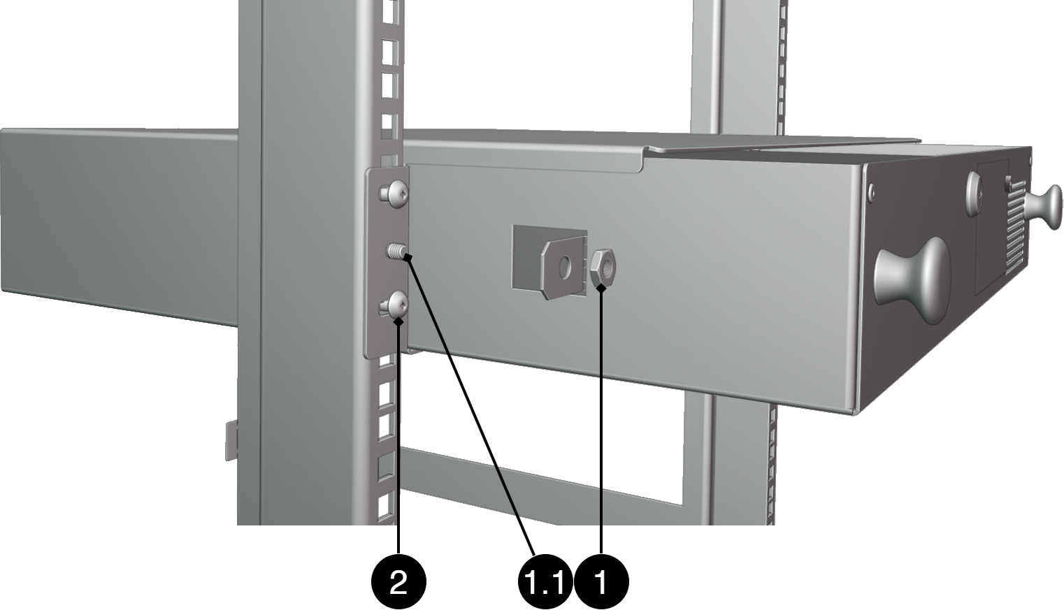
No. | Explanation |
|---|---|
1, 1.1 | Nut for fastening caps. Nut included |
2 | Screw for mounting in 19" rack. Screws are not included. |
Component overviews
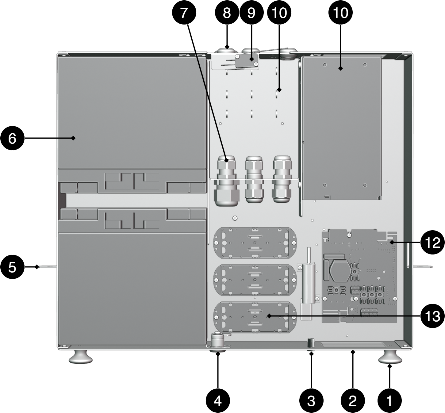
Component Overview
No. | Explanation |
|---|---|
1 | Knob to pull out the box. |
2 | Enclosure sheet. |
3 | Indication diode. |
4 | Lock. |
5 | Bracket for nut in 19" rack stand. |
6 | Place for batteries. Batteries are not included but ordered separately |
7 | Strain relief for wiring. |
8 | Cable grommets. |
9 | Tampering contact, not securely included in all configurations. |
10 | Place for cable ties to strip cable. |
11 | Power supply, varies with configuration. |
12 | Motherboard, varies with configuration. |
13 | Optional card location, optional availability varies with configuration. |
CEO-FLX
Motherboard - description
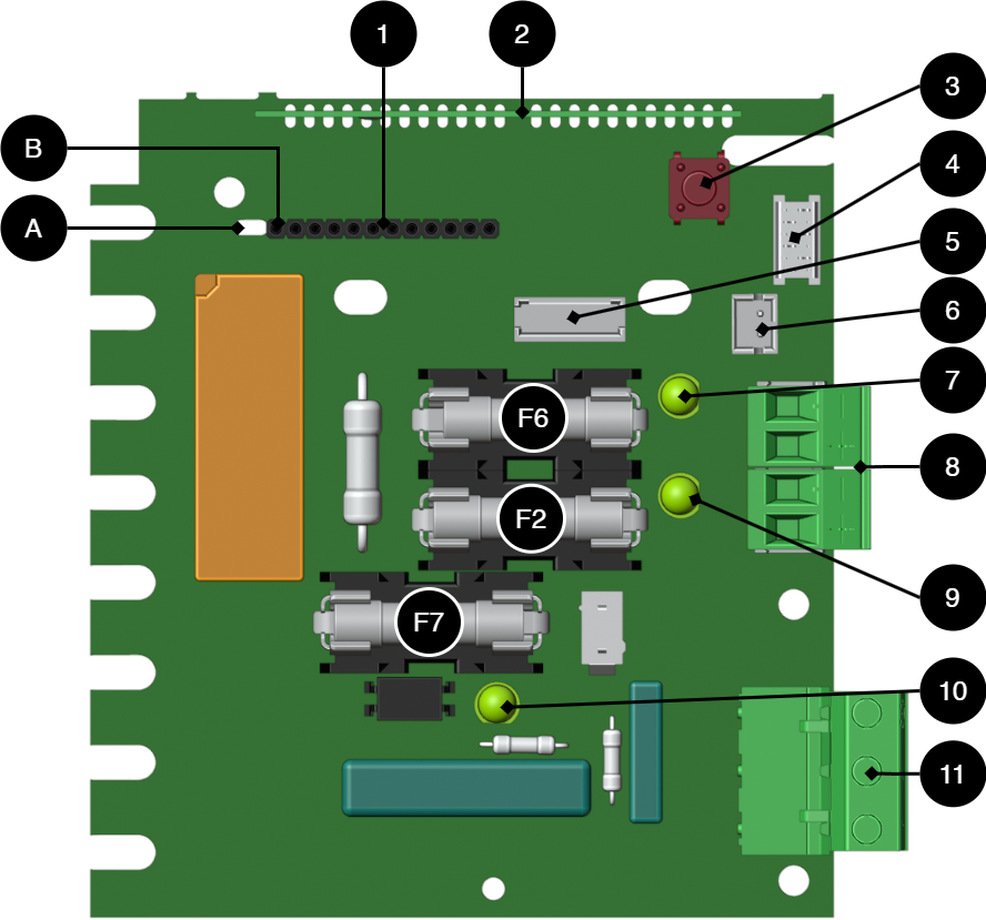
No. | On PCB | Explanation |
|---|---|---|
A | - | Holes for struts on communication boards. |
B | - | Sleeve strip for connecting communication cards. |
1 | - | Optional cards for communication. |
2 | - | CPU card. |
3 | S1 | Push button for starting with batteries only. |
4 | J39 | Connection to power stages. |
5 | J31 | Fan connection. |
6 | J24 | To fuse, EXT load card. |
7 | D1 | LED, lights green at full fuse, F6, on output 1 |
8 | J33 and J14 | Load outputs +/-. |
9 | D16 | LED, green on fuse, F2, on output 1 |
10 | D10 | LED, lights green when mains voltage is applied. |
11 | J23 | Connection mains, 230 V AC in. |
Designation | Fuse | Explanation |
|---|---|---|
F7 | T16A | Battery fuse. |
F2, F6 |
| Load fuse, +. |
Warning for replacing fuses (current strength, A)
There is a risk of damage if the fuse is changed to a larger one than what the unit is delivered with. The function of the fuse is to protect the connected load and cables against damage and fire. It is not possible to change the fuse to a larger one to increase the power output.
Connect the mains to the motherboard (PCB)
Connect mains
Before connecting, the supply circuit should be disconnected and voltage-free. Verify that the conductor area and cable type meet the applicable installation rules and that the strain relief and insulation levels comply with the requirements for 230 V AC
After connection, all screw connections should be checked and tightened. Tensioning shall only take place after mechanical protection, caps and housing have been reassembled and comply with the contact protection according to EN 62368-1
Secure F and N with cable ties.
Important
Protective earth (PE) must be connected to the PE terminal on the motherboard. The motherboard is grounded via its mounting points in the enclosure, ensuring proper potential equalization between PCB and enclosure. Also the cover is grounded through ground cable/earth braid between cover and enclosure to maintain continuity and EMC
Mains wiring must be kept separate from other wiring to avoid EMC interference.
The protective earth (PE) must be connected to the PE terminal on the motherboard. The motherboard is grounded via its mounting points in the enclosure, ensuring correct equipotential bonding between the circuit board and the enclosure. The cover is also grounded via a grounding cable / grounding braid between the cover and the enclosure to maintain continuity and EMC function.
Check that the marking on the circuit board matches the wiring order on the terminal block.
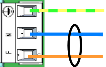
Connect the mains cable to the terminal block before it is re-inserted into the motherboard. Secure L (F in picture) and N with cable ties for electrical safety.
Letter | Explanation |
|---|---|
L | Fas |
N | Neutral |
PE |
Filter Capacitors
The products are supplied with the following filter capacitors for standard networks (TN/TT):
Type | Location |
|---|---|
X2 | Phase — Zero (L—N) |
Y2 | Phase/Zero — Protective ground (one per conductor) |
IT Networking
IT networks generate higher transients as the system works phase to phase. Therefore, according to the current standard, capacitors of a higher class are required
Departure from X1/Y1 capacitors can be done but then external transient protection must be installed. For devices to be installed in IT networks, Milleteknik's lightning protection must be fitted to maintain standards.
On circuit boards | Terminal No. | Explanation |
|---|---|---|
+ LOAD - | J33 | Connection for load +/-. |
+ LOAD - | J14 | Connection for load +/-. |
Max current
The maximum current must not be exceeded. Max current is indicated on the rating plate on the device.
Batteries - placement and connection
Connecting batteries
Caution
Batteries can wear out faster than expected when temperatures fall outside the range that is optimal for battery operation.
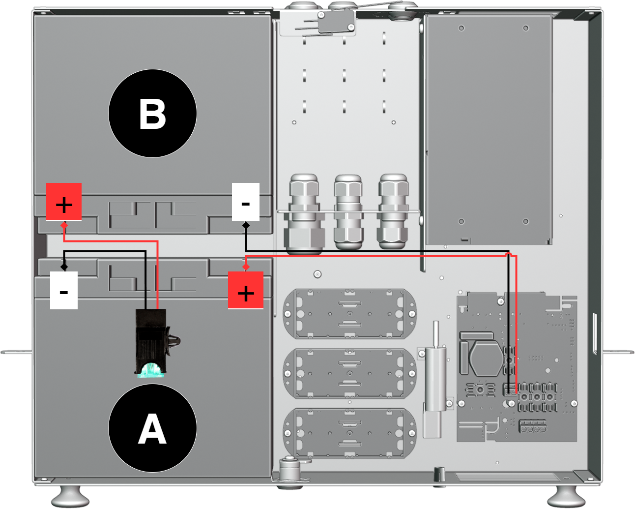
Important
Cover the poles of battery B before mounting battery A. It reduces the risk of short circuit during assembly
Check that the mains voltage is disconnected before connecting batteries.
Check the polarity of the batteries.
Connect the black battery cable to the negative terminal (-) of the battery B.
Install fuse holder on battery B.
Connect red battery cable to battery A's plus pole (+).
Connect fuse holder on battery A.
Install the battery fuse in the fuse holder.
Make sure that all connections are securely attached and that the polarity is correct.
To deploy the device, follow the steps for deployment.
Deployment - how to start the device
Danger
Personal injury or death can occur if the device is connected to the mains or live when disassembling / moving.
Connect load.
Connect batteries.
Connect mains voltage.
Plug in mains voltage.
Alarm displayed on cabinet door
In normal mode, the indicator LED shows a solid green light.
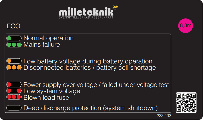 |
Indicator diode shows | Text on the panel | Explanation |
|---|---|---|
Solid green light | Normal operation | The system is in normal operation. Mains voltage is available and the battery is fully charged. |
Slow green flashes | N/A | Not present in this model. |
Quick green flashes | Mains failure | .Mains power is lost. The unit is running on battery. Check the mains supply. |
Solid amber light | Low battery voltage during battery operation | The battery voltage is low during battery operation. The system will soon shut down when batteries are discharged. |
Slow amber flashes | N/A | Not present in this model. |
Quick amber flashes | Batteries disconnected | The battery is not connected or has a bad contact. Check battery cables and fuses |
Solid red light | Power supply over-voltage, failed under-voltage test | The power supply has an incorrect input voltage or is out of tolerance. Check the voltage of the power supply. |
Slow red flashes | Low system voltage | The system voltage is low. This may be due to high load, a discharged battery, or other system issues. |
Quick red flashes | Blown load fuse | A load fuse has loosened. Check the load and replace the fuse if necessary |
Black/Off | Deep discharge protection | In the event of a deep discharge, the unit shuts down and the LED goes out. This is normal and protects the batteries. Mains power must be restored to restart. |
When operating system: If the indicator LED is off, deep discharge protection has been activated.
Notice
If the indicator light flashes every 15 seconds, the battery is fully charged and the charge is in rest phase to extend battery life. In the event of a power failure during the rest phase, the battery backup switches to battery operation as usual
Maintenance
Safety Information - Service and Troubleshooting
If possible, disconnect the mains supply before starting any work, such as servicing, battery replacement, metering or troubleshooting.
Remove the battery fuse/plug before working on the DC side.
Check that all cables are properly connected and grounded before re-energizing the unit.
The product may contain components that become hot during operation. Avoid touching internal parts immediately after the power has been switched off.
If fuses blow repeatedly see Troubleshooting or disconnect the unit and contact Milleteknik technical support.
In case of suspicion of damage, liquid ingress or burnt odour, the product must not be used until it has been inspected by qualified personnel.
During operation, the housing should be closed and locked (if the device has a lock).
Only authorized service personnel may perform repairs on the device.
Use only original fuses and batteries of the same type and value as specified in the manual/product sheet.
Milleteknik is not responsible for damage caused by improper handling, modification or unapproved components.
Troubleshooting
If the device does not work as expected, go through the following checks:
Problem | Possible cause | Action |
|---|---|---|
No output voltage. | No mains voltage, fuse triggered or battery failure. | Check the supply, fuses and battery connections. |
Battery does not charge. | Faulty battery connection or battery fuse has blown. | Check battery cables and replace battery fuse if necessary. |
The device starts but alarms. | Batteries not sufficiently charged or faulty load or battery. | Wait 72 hours until the batteries are fully charged. Ensure that the connected load does not exceed the rated current. |
LED flashes. | Information, warning or error. | See panel or manual for explanation. |
Fuses blow frequently. | Short circuit or overload. | Check connected devices, change the fuse only after the cause has been resolved. |
Unit overheating | High load or insufficient ventilation | Check that the rated current is not exceeded and ensure adequate ventilation around the enclosure. |
Control measurement of batteries
In case of troubleshooting, the voltage of the batteries can be checked using a multimeter. Measure each 12V battery separately over the plus and minus pole. Next, measure the entire battery group connected in series. Two 12 V batteries connected in series should provide approximately 24-27 V DC depending on the degree of charge and whether charging is in progress. If measured voltage is significantly lower than expected, check polarity, battery fuse and wiring between battery box and battery backup.
If the problem persists after these checks, contact Milleteknik support and provide the product name, serial number, and a brief description of the fault.
Product sheet - power supply / battery backup
Product Sheet
ECO power supply with battery backup
Item Information
The table shows the name, part number and email number of the product
Product Identification
Product designation | Article number | E-number (SE) |
|---|---|---|
ECO 24V 5A 2HE | 2U02C10424P050 | 52 137 89 |
Technical description
Compact rack-mounted battery backup in 2 HE with 24 V, 5A and space for 2 × 12 V 20 Ah batteries, optimized for mounting in 19" racks.
Areas of application
Areas of application | Yes | No |
|---|---|---|
Burglar alarm | ✔ | |
Designed for backup power to access systems and security applications in 19" racks where compact installation is required. | ✔ |
Electrical data
Electrical data | |
|---|---|
Supply voltage | 230V AC, +/- 10%, 47Hz- 63Hz |
Charge current | Depending on the power outlet. Max 1.5A Max 5 A |
Voltage out | 27.3 V DC, (24 V DC) |
Load outputs
Alarm and protection
Communication and Indications

The PowerWatch is available as an option for the product.
Battery
Enclosure and Mechanics
Enclosure and Mechanics | |
|---|---|
Type | Enclosure for 19" rack |
IP class | IP20 |
Material | |
Colour | Black |
Height units | 2 |
Cable grommets | 6 pcs |
Lock | ✔ 2 keys included |
Fan in enclosure | ✘ |
Assembly, installation and eligibility requirements
Fitting | Yes | No |
|---|---|---|
19" rack. | ✔ |
Installation | Yes | No |
|---|---|---|
Fixed installation. | ✔ |
Dimensions, weight and packaging information
Net weight | Weight with packaging |
|---|---|
7.0 kg | 7.3 kg |
Packaging | |
|---|---|
Packaging |
|
Quantity in pack | 1 pc. |
Packaging Type (GS1 T0137) | BX box. |
Conditions EUR pallet | EUR pallets may not be stacked during transport or storage. Stacking may result in damage to product and packaging |
Transport environment | The product must be protected from condensation and direct precipitation during transportation. |
Transport temperature (without battery) | −30 °C to +70 °C |
Storage environment | Dry indoor environment, protected from condensation. Relative humidity: max 95%, non-condensing |
Storage temperature without batteries | −20 °C to +60 °C |
Contact
Department | |
|---|---|
Switchboard | 031-340 02 30 |
Support and technical issues | support@milleteknik.se |
Sales | sales@milleteknik.se |
WWW | www.milleteknik.se |
Address | Ögärdesvägen 8B, 433 30 Partille |
About this information
All information is published subject to possible errors. Information is updated without prior notice. |
Publication date 2026-06-29
Compliance and regulatory compliance
Delivery time, warranty and terms
Delivery time, warranty and terms | |||||||||||||||||||||||||||||||||||||||||||||||||
|---|---|---|---|---|---|---|---|---|---|---|---|---|---|---|---|---|---|---|---|---|---|---|---|---|---|---|---|---|---|---|---|---|---|---|---|---|---|---|---|---|---|---|---|---|---|---|---|---|---|
Warranty period[a] | The product has a two (2) year warranty against manufacturing defects. | ||||||||||||||||||||||||||||||||||||||||||||||||
Special warranty conditions | See also general terms and conditions. | ||||||||||||||||||||||||||||||||||||||||||||||||
General Terms and Conditions | ALEM09 with exceptions, see: www.milleteknik.se/conditions/ | ||||||||||||||||||||||||||||||||||||||||||||||||
Support | Telephone support and email support during the warranty period are free of charge. For spare parts that are not covered by warranty, there is a charge | ||||||||||||||||||||||||||||||||||||||||||||||||
Delivery and stock | |||||||||||||||||||||||||||||||||||||||||||||||||
Delivery time[b] | Or as per agreement. Delivery from factory, transportation time is added. | ||||||||||||||||||||||||||||||||||||||||||||||||
[a] If the device is purchased through a wholesaler or other supplier, other warranty conditions may apply [b] In the case of larger orders, delivery time increases, acc. to agreement. | |||||||||||||||||||||||||||||||||||||||||||||||||
Operation and maintenance
Operation | Data | Other. info | |||||||||||||||||||||||||||||||||||||||||||||||
|---|---|---|---|---|---|---|---|---|---|---|---|---|---|---|---|---|---|---|---|---|---|---|---|---|---|---|---|---|---|---|---|---|---|---|---|---|---|---|---|---|---|---|---|---|---|---|---|---|---|
Environment | |||||||||||||||||||||||||||||||||||||||||||||||||
Operating temperature (recommended) | +15°C to +25°C | ||||||||||||||||||||||||||||||||||||||||||||||||
Operating temperature (permissible)[a] | +5°C to +40°C | Class 1 according to EN 50131-6/ EN 60839-11 | |||||||||||||||||||||||||||||||||||||||||||||||
Load, power supply | 80% | Average load shall not exceed 80% of the rated capacity of the power supply. | |||||||||||||||||||||||||||||||||||||||||||||||
Ventilation, in front and behind the enclosure. | 100 mm | Ventilation openings must not be blocked or covered. | |||||||||||||||||||||||||||||||||||||||||||||||
[a] Specifies the permissible ambient temperature range in which the product can operate without damage. See also table on battery life. | |||||||||||||||||||||||||||||||||||||||||||||||||
Yes | No | Interval | Other. info |
|---|---|---|---|
✔ | Annually | Battery terminal voltage must be measured. Ensure that the average load does not exceed 80% of the rated capacity of the power supply. |
Certifications and approvals
Complies with | Directives |
|---|---|
Emissions | |
Immunity | EN61000-6-2:2005, EN61000-4-2, -3, 4, -5, -6, -11 SS-EN 50130-4:2011 Edition 2, EN50131-6 |
C.E. | CE marking according to (EC) 765/2008 |
EMC | EMC Directive 2014/30EU |
Electric (LVD) | Low Voltage Directive: 2014/35/EU |
Environmental data
Environmental data | J/N | Informație | Other. info. | ||||||||||||||||||||||||||||||||||||||||||||||
|---|---|---|---|---|---|---|---|---|---|---|---|---|---|---|---|---|---|---|---|---|---|---|---|---|---|---|---|---|---|---|---|---|---|---|---|---|---|---|---|---|---|---|---|---|---|---|---|---|---|
Building Product Declaration (BPD) | ✔ | Yes, see iBvd at www.milleteknik.se. | - | ||||||||||||||||||||||||||||||||||||||||||||||
REACH Information Obligation (EC) No 1907/2006 | ✔ | If empty, the product is not covered. | |||||||||||||||||||||||||||||||||||||||||||||||
SVHC substances, CAS/EC | ✔ | For text, see iBvd at www.milleteknik.se. If blank, substance is missing. | |||||||||||||||||||||||||||||||||||||||||||||||
Subject to the RoHS Directive, (EU) 2015/863) | ✔ | ||||||||||||||||||||||||||||||||||||||||||||||||
WEEE 2012/19/EU | ✔ | If empty, the product is not covered. End-of-life products must be returned to a recycling centre | |||||||||||||||||||||||||||||||||||||||||||||||
Battery Regulation (EU) 2023/1542 | |||||||||||||||||||||||||||||||||||||||||||||||||
SCIP No 2008/98/EC | ✔ | If empty, no SCIP number is needed. | |||||||||||||||||||||||||||||||||||||||||||||||
Conflict minerals (EU) 2017/821 | ✗/✗/✗/✗/✔ | No=Gold, Tungsten, Tantalum, Cobalt. Yes=Tin | Tin in solders in printed circuit boards purchased through a Swedish supplier. | ||||||||||||||||||||||||||||||||||||||||||||||
Contains nanomaterials: EC 1272/2008 | ✗ | The product does not contain nanomaterials. | |||||||||||||||||||||||||||||||||||||||||||||||
Ecodesign 2009/125/EC | Milleteknik's products are intended for professional use and are therefore not directly covered by the Ecodesign Regulation (EU 2019/1782). As some components may be covered, we nevertheless disclose relevant information[a], where applicable, to provide our customers with confidence in their choice. | ||||||||||||||||||||||||||||||||||||||||||||||||
Machine Directive 2006/42/EC | The product is part of electrical systems, is subject to the relevant electrical and safety directives and is not a machine according to the Machinery Directive (2006/42/EC). Will be replaced by Machinery Regulation (EU) 2023/1230, which will apply in 2027. | ||||||||||||||||||||||||||||||||||||||||||||||||
[a] Standby consumption and power. | |||||||||||||||||||||||||||||||||||||||||||||||||

Manufacturer and country of origin
Appendix
Backup operating time on batteries
The reserve operating time in battery operation depends on how large a load is connected to the power supply. If the load varies, as with frequent opening of door locks, the time that batteries can continue to power the security system decreases. To get an estimate of reserve operating times see: www.milleteknik.se/Manualer/FaQ/Reservdrifttider/
PowerWatch
Product designation | Item No. | E-number (SE) |
|---|---|---|
PowerWatch | A-OT0000UPG02P2V3P3 | 52 137 06 |
Alarms that can be set in PowerWatch |
|---|
Charger failure, overvoltage |
Charger failure, undervoltage |
Fan failure, (in case of externally connected fan) |
Fuse failure on load |
Low battery voltage, in battery operation |
Power outage, delay 10 seconds |
Unconnected battery |
Unit not calibrated |
Eligibility requirements, installation
Eligibility requirements vary between countries. The table summarizes national requirements for fixed installation and connection of equipment with a plug socket, respectively.
Options on the secondary side of the product, such as 12 V, 24 V or 48 V DC, are connected according to the respective instructions. Work on the network connection of the product shall be carried out in accordance with national eligibility requirements
Permission Requirements for Installation | Fixed installation (230 V) | Plug | Other. info |
|---|---|---|---|
Sweden | ✔ | ✗ | Fixed installation may be performed by technicians but shall be under the responsibility of a qualified installer. (Electrical Safety Act, SS 436 40 00) Plug may be connected without authorization. |
Norway | ✔ | ✔ | Requirements for qualified electricians also for equipment with a plug socket in fixed installations. (NEK 400, DSB |
Finland | ✔ | ✗ | Plug may be connected without authorization. (Tukes, SFS 6000 |
Denmark | ✔ | ✗ | Plug may be connected without authorization. (Safety Board |
Germany | ✔ | ✗ | All fixed installations require a qualified electrician according to VDE 0100. Plug sockets may be connected without authorization, but only by person with basic electrical knowledge (“Elektrotechnisch unterwiesene Person”) |
Reference table: environmental classes according to EN 50130-5 (referred to in EN 50131-6)
Class | Type | Temperature range |
|---|---|---|
Environmental Class 1 | Heated indoors (type office/residence). | +5°C to +40°C |
Environmental Class 2 | Generally indoors (type warehouses/stairwells, not temperature controlled). | -10°C to +40°C |
Environmental class 3 | Protected outdoors. | -25°C to +50°C |
Environmental class 4 | Generally outdoors. | -25°C to +60°C |
Reference table: manufacturer's stated service life and recommended battery replacement
Battery Type (Design Life)[a] | Battery replacement time in normal operation, +20°C. | Replacement during hot operation, +30°C | Replacement during hot operation, +40°C | ||||||||||||||||||||||||||||||||||||||||||||||
|---|---|---|---|---|---|---|---|---|---|---|---|---|---|---|---|---|---|---|---|---|---|---|---|---|---|---|---|---|---|---|---|---|---|---|---|---|---|---|---|---|---|---|---|---|---|---|---|---|---|
3 - 5 years | 2 - 3 years | 1 - 1.5 years | 0.5 - 0.75 years | ||||||||||||||||||||||||||||||||||||||||||||||
6 - 9 years | 5 - 6 years | 2.5 - 3 years | 1.2 - 1.5 years | ||||||||||||||||||||||||||||||||||||||||||||||
10 - 12 years | 6 - 7 years | 3 - 3.5 years | 1.5 - 1.75 years | ||||||||||||||||||||||||||||||||||||||||||||||
15 + years | 10 - 12 years | 5 - 6 years | 2.5 - 3 years | ||||||||||||||||||||||||||||||||||||||||||||||
[a] Valid in case of completely unused battery stored under optimal conditions. | |||||||||||||||||||||||||||||||||||||||||||||||||
About this information
All information is published subject to possible errors. Information is updated without prior notice. |
Publication date 2026-06-29
Address and contact details
Milleteknik AB |
Ögärdesvägen 8 B |
S-433 30 Partille |
Sweden |
+46 31 340 02 30 |
info@milleteknik.se |
www.milleteknik.com |
[1] Translations in languages other than Swedish are indicative only and not verified. Translation should always be checked against the Swedish original to ensure accurate information