
Installation and commissioning
Instructions for installation and commissioning.
Product Identification
Product designation | Item No. | E-number (SE) (sv) |
|---|---|---|
Relay/Communication Cards ECO Series (CEO-FLX) | A-AL1224CEO01 | 52 137 85 |
Product image
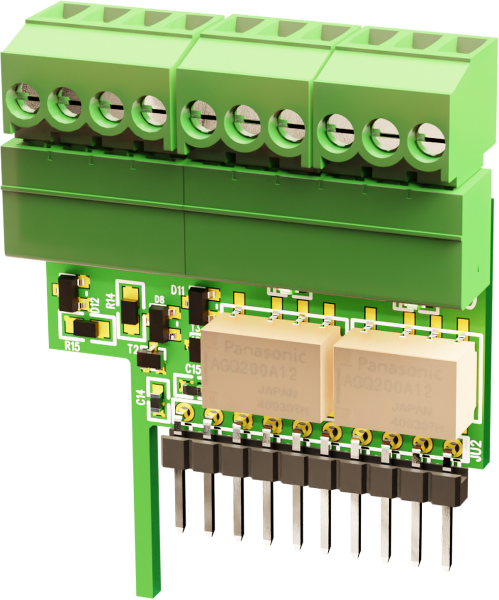
Technical description
Alarm and communication card intended as an option for ECO series products with CEO-FLX motherboards. The card is used to transmit alarm, status and monitoring information between the ECO device and external systems. It is equipped with two relay outputs (NO/NC/COM). One relay signals a power outage, and the other acts as a buzzer alarm (fuse failure as factory default). Both relay outputs can be set and customized via PowerWatch depending on your needs. The card is fully compatible with PowerWatch. Installing the board enables configuration and monitoring from the ECO unit to the PowerWatch, providing extended functionality for operational control and event management. The alarm and communication board is mounted directly on the CEO-FLX board. It is intended for installations where flexible
Quick Facts | |
|---|---|
Supply voltage (V) | 27.3 V DC (24 V DC) or 13.6 V DC (12 V DC) |
Accessories for | Outdoor Enclosures. |
Where does the card fit?
The table shows where Relay/Communication Cards ECO Series (CEO-FLX) fit in for power supply.
Name | Item No. | E-number |
|---|---|---|
ECO 24V 10A M | ME01C10424P100 | 52 137 83 |
ECO 24V 5A L | LA01C10424P050 | 52 137 81 |
ECO 24V 10A L | LA01C10424P100 | 52 137 82 |
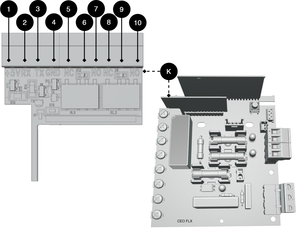
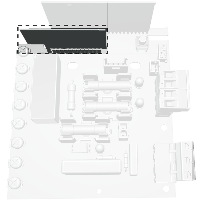
Alarm and communication board installation and card description
The alarm card is used to transmit alarm and status information between the CEO-FLX card and external systems. It provides the ability to send alarms via relay outputs as well as
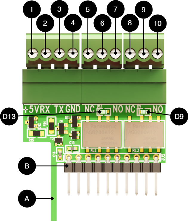
No. | On the PCB | Explanation |
|---|---|---|
K | - | Alarm board that mounts to the CEO-FLX board, as the picture shows. |
A | - | Support pillar for stability and to prevent incorrect connection. |
B | - | Pin strip. |
D13 | D13 | LED indicates relay idle state (green lit). |
D9 | D9 | LED indicates relay idle state (green lit). |
1 | +5V | Connection to PowerWatch. |
2 | RX | |
3 | TX | |
4 | GND | |
5 | NC | Relay output 1 — normally closed (breaking contact). |
6 | COM | Relay output 1 — common contact. |
7 | NO | Relay output 1 — Normally Open (closing contact). |
8 | NC | Relay output 2 — normally closed (breaking contact). |
9 | COM | Relay output 2 — common contact. |
10 | NO | Relay output 2 — normally open (closed contact). |
Plug in alarm
Alarms are plugged into terminal block, see circuit board overview.
No. | On the Map | Alarm type | Explanation | ||||||||||||||||||||||||||||||||||||||||||||||
|---|---|---|---|---|---|---|---|---|---|---|---|---|---|---|---|---|---|---|---|---|---|---|---|---|---|---|---|---|---|---|---|---|---|---|---|---|---|---|---|---|---|---|---|---|---|---|---|---|---|
5 | NC | Mains failure alarm (10 seconds delay).[a] | Relay output 1 — normally closed (breaking contact). | ||||||||||||||||||||||||||||||||||||||||||||||
6 | COM | Relay output 1 — common contact. | |||||||||||||||||||||||||||||||||||||||||||||||
7 | NO | Relay output 1 — normally open (closed contact). | |||||||||||||||||||||||||||||||||||||||||||||||
8 | NC | Summary alarm, Fuse failure as factory reset.[b] | Relay output 2 — normally closed (breaking contact). | ||||||||||||||||||||||||||||||||||||||||||||||
9 | COM | Relay output 2 — common contact. | |||||||||||||||||||||||||||||||||||||||||||||||
10 | NO | Relay output 2 — normally open (closed contact). | |||||||||||||||||||||||||||||||||||||||||||||||
[a] Factory setting, adjustable in PowerWatch [b] Factory setting, adjustable in PowerWatch. | |||||||||||||||||||||||||||||||||||||||||||||||||
Plug in PowerWatch
PowerWatch plugs into terminal block, see circuit board overview.
No. | On the Map | Explanation |
|---|---|---|
1 | +5V | Connection to PowerWatch. |
2 | RX | |
3 | TX | |
4 | GND |
Fitting
Tip
The battery backup does not normally need to be voltage-free during assembly. Be careful not to short-circuit any component
Plug in alarms before mounting the board.
Press the card firmly onto the motherboard in the battery backup. Make sure the strut (A) slides frictionlessly before fully depressing the board
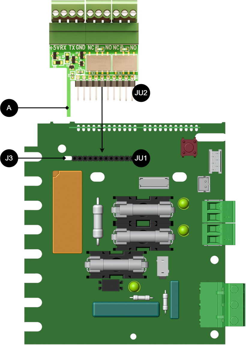
Letter/ on printed circuit board | Explanation |
|---|---|
JU1 | Pin strip on control board. |
J3 | Hole for brace (A). |
A | Strut. |
JU2 | Pin strip on relay/communication board. |
When the board is assembled, it sits in front of the vertical board on the control board.
Product sheet - power supply / battery backup
Product Sheet
Product image
Item Information
The table shows the name, part number and email number of the product
Product Identification
Product designation | Item No. | E-number (SE) (sv) |
|---|---|---|
Relay/Communication Cards ECO Series (CEO-FLX) | A-AL1224CEO01 | 52 137 85 |
Technical description
Alarm and communication card intended as an option for ECO series products with CEO-FLX motherboards. The card is used to transmit alarm, status and monitoring information between the ECO device and external systems. It is equipped with two relay outputs (NO/NC/COM). One relay signals a power outage, and the other acts as a buzzer alarm (fuse failure as factory default). Both relay outputs can be set and customized via PowerWatch depending on your needs. The card is fully compatible with PowerWatch. Installing the board enables configuration and monitoring from the ECO unit to the PowerWatch, providing extended functionality for operational control and event management. The alarm and communication board is mounted directly on the CEO-FLX board. It is intended for installations where flexible
Quick Facts | |
|---|---|
Supply voltage (V) | 27.3 V DC (24 V DC) or 13.6 V DC (12 V DC) |
Accessories for | Outdoor Enclosures. |
Areas of application
Areas of application | Yes | No |
|---|---|---|
PowerWatch compatible | ✔ | |
Provides functionality that enables alarm class 2 together with compatible ECO products. | ✔ | |
Alarm transmission/alarm on switching relay | ✔ |
Electrical data
Electrical data | |
|---|---|
Supply voltage | 27.3 V DC (24 V DC) or 13.6 V DC (12 V DC) |
Standby consumption | Data is missing. |
Circuit Boards | Internal power consumption | Other. info |
|---|---|---|
Relay/Communication ECO (CEO-FLX) | Data is missing |
Alarm and protection
Communication and Indications
Enclosure and Mechanics
Enclosure and Mechanics | |
|---|---|
Type | Printed circuit board, product does not have enclosure |
Assembly, installation and eligibility requirements
Fitting | Yes | No |
|---|---|---|
In product (optionally fitted in compatible product). | ✔ |
Installation | Yes | No |
|---|---|---|
Installed in product. | ✔ |
Dimensions, weight and packaging information
Net weight | Weight with packaging |
|---|---|
0.1 kg | 0.2 kg |
Packaging | |
|---|---|
Packaging | Cardboard and impact protection in cardboard. |
Quantity in pack | 1 pc. |
Packaging Type (GS1 T0137) | BX box. |
Conditions EUR pallet | EUR pallets may not be stacked during transport or storage. Stacking may result in damage to product and packaging |
Transport environment | The product must be protected from condensation and direct precipitation during transportation. |
Transport temperature (without battery) | −30 °C to +70 °C |
Storage environment | Dry indoor environment, protected from condensation. Relative humidity: max 95%, non-condensing |
Storage temperature without batteries | −20 °C to +60 °C |
The accessories fits in
Contact
Department | |
|---|---|
Switchboard | 031-340 02 30 |
Support and technical issues | support@milleteknik.se |
Sales | sales@milleteknik.se |
WWW | www.milleteknik.se |
Address | Ögärdesvägen 8B, 433 30 Partille |
About this information
All information is published subject to possible errors. Information is updated without prior notice. Milleteknik with the associated logo is a trademark of Milleteknik AB. PowerWatch is a trademark of Milleteknik AB. |
Publication date 2026-07-09
Compliance and regulatory compliance
Delivery time, warranty and terms
Delivery time, warranty and terms | |||||||||||||||||||||||||||||||||||||||||||||||||
|---|---|---|---|---|---|---|---|---|---|---|---|---|---|---|---|---|---|---|---|---|---|---|---|---|---|---|---|---|---|---|---|---|---|---|---|---|---|---|---|---|---|---|---|---|---|---|---|---|---|
Warranty period[a] | The product has a two (2) year warranty against manufacturing defects. | ||||||||||||||||||||||||||||||||||||||||||||||||
Special warranty conditions | See also general terms and conditions. | ||||||||||||||||||||||||||||||||||||||||||||||||
General Terms and Conditions | ALEM09 with exceptions, see: www.milleteknik.se/conditions/ | ||||||||||||||||||||||||||||||||||||||||||||||||
Support | Telephone support and email support during the warranty period are free of charge. For spare parts that are not covered by warranty, there is a charge | ||||||||||||||||||||||||||||||||||||||||||||||||
Delivery and stock | |||||||||||||||||||||||||||||||||||||||||||||||||
Delivery time[b] | 2 working days. Or as per agreement. Delivery from factory, transportation time is added. | ||||||||||||||||||||||||||||||||||||||||||||||||
[a] If the device is purchased through a wholesaler or other supplier, other warranty conditions may apply. [b] In the case of larger orders, delivery time increases, acc. to agreement. | |||||||||||||||||||||||||||||||||||||||||||||||||
Operation and maintenance
Operation | Data | Other. info | |||||||||||||||||||||||||||||||||||||||||||||||
|---|---|---|---|---|---|---|---|---|---|---|---|---|---|---|---|---|---|---|---|---|---|---|---|---|---|---|---|---|---|---|---|---|---|---|---|---|---|---|---|---|---|---|---|---|---|---|---|---|---|
Environment | Indoor environmental class 1. | ||||||||||||||||||||||||||||||||||||||||||||||||
Operating temperature (recommended) | +15°C to +25°C | ||||||||||||||||||||||||||||||||||||||||||||||||
Operating temperature (permissible)[a] | +5°C to +40°C | Class 1 according to EN 50131-6/ EN 60839-11 | |||||||||||||||||||||||||||||||||||||||||||||||
[a] Specifies the permissible ambient temperature range in which the product can operate without damage. See also table on battery life. | |||||||||||||||||||||||||||||||||||||||||||||||||
Yes | No | Interval | Other. info |
|---|---|---|---|
✔ | Maintenance-free. |
Certifications and approvals
Complies with | Directives |
|---|---|
Emissions | |
Immunity | EN61000-6-2:2005, EN61000-4-2, -3, 4, -5, -6, -11 SS-EN 50130-4:2011 Edition 2, EN50131-6 |
C.E. | CE marking according to Regulation (EC) No 765/2008 |
RoHS | RoHS Directive 2011/65/EU, including amendment (EU) 2015/863 |
EMC | EMC Directive 2014/30/EU |
Electric (LVD) | Low Voltage Directive 2014/35/EU |
Environmental data
Environmental data | J/N | Informație | Other. info. | ||||||||||||||||||||||||||||||||||||||||||||||
|---|---|---|---|---|---|---|---|---|---|---|---|---|---|---|---|---|---|---|---|---|---|---|---|---|---|---|---|---|---|---|---|---|---|---|---|---|---|---|---|---|---|---|---|---|---|---|---|---|---|
Building Product Declaration (BPD) | ✔ | Yes, see iBvd at www.milleteknik.se. | - | ||||||||||||||||||||||||||||||||||||||||||||||
REACH Information Obligation (EC) No 1907/2006 | ✔ | Yes, see the DoC at www.milleteknik.se The product complies with REACH Regulation (EC) No 1907/2006. | If empty, the product is not covered. | ||||||||||||||||||||||||||||||||||||||||||||||
SVHC substances, CAS/EC | ✔ | Yes, lead, 7439-92-1/231-100-4 | For text, see iBvd at www.milleteknik.se. If blank, substance is missing. | ||||||||||||||||||||||||||||||||||||||||||||||
Subject to the RoHS Directive, (EU) 2015/863) | ✔ | Yes, see the DoC at www.milleteknik.se | |||||||||||||||||||||||||||||||||||||||||||||||
WEEE 2012/19/EU | ✔ | The product contains electrical components or wiring and is covered by the WEEE Directive (2012/19/EU). | If empty, the product is not covered. End-of-life products must be returned to a recycling centre | ||||||||||||||||||||||||||||||||||||||||||||||
Battery Regulation (EU) 2023/1542 | ✗ | ||||||||||||||||||||||||||||||||||||||||||||||||
SCIP No 2008/98/EC | ✔ | If empty, no SCIP number is needed. | |||||||||||||||||||||||||||||||||||||||||||||||
Conflict minerals (EU) 2017/821 | ✗/✗/✗/✗/✔ | No=Gold, Tungsten, Tantalum, Cobalt. Yes=Tin | Tin in solders in printed circuit boards purchased through a Swedish supplier. | ||||||||||||||||||||||||||||||||||||||||||||||
Contains nanomaterials: EC 1272/2008 | ✗ | The product does not contain nanomaterials. | |||||||||||||||||||||||||||||||||||||||||||||||
Ecodesign 2009/125/EC | Milleteknik's products are intended for professional use and are therefore not directly covered by the Ecodesign Regulation (EU 2019/1782). As some components may be covered, we nevertheless disclose relevant information[a], where applicable, to provide our customers with confidence in their choice. | ||||||||||||||||||||||||||||||||||||||||||||||||
Machine Directive 2006/42/EC | The product is part of electrical systems, is subject to the relevant electrical and safety directives and is not a machine according to the Machinery Directive (2006/42/EC). Will be replaced by Machinery Regulation (EU) 2023/1230, which will apply in 2027. | ||||||||||||||||||||||||||||||||||||||||||||||||
The product is designed for a long service life, which reduces the environmental impact. End-of-life products are handed over to the nearest recycling centre. | |||||||||||||||||||||||||||||||||||||||||||||||||
[a] Standby consumption and power. | |||||||||||||||||||||||||||||||||||||||||||||||||

Manufacturer and country of origin
Appendix
Eligibility requirements, installation
Eligibility requirements vary between countries. The table summarizes national requirements for fixed installation and connection of equipment with a plug socket, respectively.
Options on the secondary side of the product, such as 12 V, 24 V or 48 V DC, are connected according to the respective instructions. Work on the network connection of the product shall be carried out in accordance with national eligibility requirements
Permission Requirements for Installation | Fixed installation (230 V) | Plug | Other. info |
|---|---|---|---|
Sweden | ✔ | ✗ | Fixed installation may be performed by technicians but shall be under the responsibility of a qualified installer. (Electrical Safety Act, SS 436 40 00) Plug may be connected without authorization. |
Norway | ✔ | ✔ | Requirements for qualified electricians also for equipment with a plug socket in fixed installations. (NEK 400, DSB |
Finland | ✔ | ✗ | Plug may be connected without authorization. (Tukes, SFS 6000 |
Denmark | ✔ | ✗ | Plug may be connected without authorization. (Safety Board |
Germany | ✔ | ✗ | All fixed installations require a qualified electrician according to VDE 0100. Plug sockets may be connected without authorization, but only by person with basic electrical knowledge (“Elektrotechnisch unterwiesene Person”) |
Reference table: environmental classes according to EN 50130-5 (referred to in EN 50131-6)
Class | Type | Temperature range |
|---|---|---|
Environmental Class 1 | Heated indoors (type office/residence). | +5°C to +40°C |
Environmental Class 2 | Generally indoors (type warehouses/stairwells, not temperature controlled). | -10°C to +40°C |
Environmental class 3 | Protected outdoors. | -25°C to +50°C |
Environmental class 4 | Generally outdoors. | -25°C to +60°C |
About this information
All information is published subject to possible errors. Information is updated without prior notice. Milleteknik with the associated logo is a trademark of Milleteknik AB. PowerWatch is a trademark of Milleteknik AB. |
Publication date 2026-07-09