
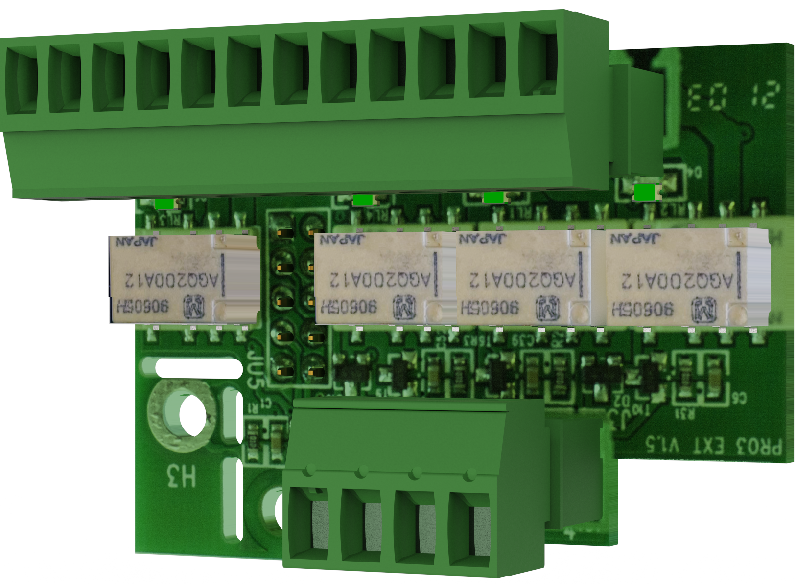
Technical specifications: Relay Card NOVA Series (PRO3)
With 4 pcs. relay outputs for systems supplied with PRO3 motherboards.
Installation and commissioning
Instructions for installation and commissioning.
Installation of Relay card NOVA Series on motherboard-PRO3
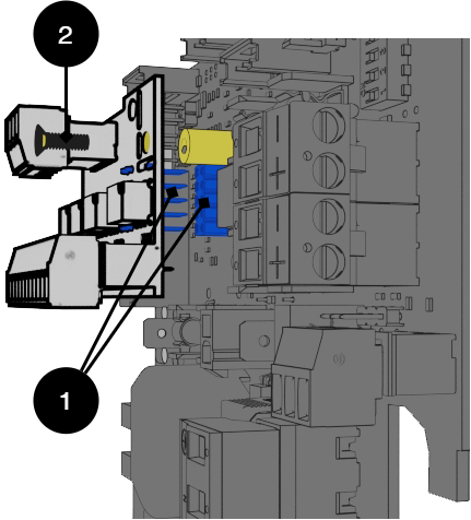 |
No | Explanation |
|---|---|
1 | Pin and pin strip for connection. |
2 | Screw to secure mounting. |
Card Description - Relay Card NOVA Series (PRO3)
Relay card - description, connections and alarm outputs.
All fault arm relays must be in the drawn state. Check that there is a gap between CO and NC. Put the measuring instrument on continuity measurement and test closure. This should then indicate a short circuit.
All relay outputs are normally live and give an alarm in the event of no voltage.
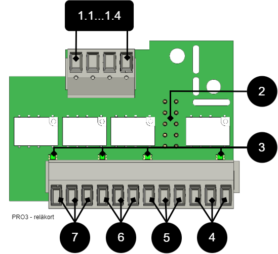 |
No . | Terminal no. | The relay is normally energized. | Alarm type / explanation |
|---|---|---|---|
1.1...1.4 | P4:1 | - | GND, protective earth |
P4:2 | - | RX | |
P4:3 | - | TX | |
P4:4 | - | +5V | |
2 | JU5 | - | Connection to motherboard. |
3 | D2-D6 | - | Indicator diode, lit green when OK. |
4 | P5:10-12 | NC, COM, NO | Alarm from tamper switch, (optional for NEO and EN54). |
5 | P5:7-9 | NC, COM, NO | Low system voltage. |
6 | P5:4-6 | NC, COM, NO | Alarm for fuse failure, charger failure overvoltage, charger failure undervoltage, battery not connected, low battery voltage in case of mains failure and aged battery*. *NOVA only. |
7 | P5:1-3 | NC, COM, NO | Mains failure alarm. |
Technical data, alarm card for PRO 3 / NEO3
Info | Explanation |
|---|---|
Card name: | PRO 3 |
Version: | 1.2 |
Product description | Motherboard in battery backup with advanced functions and communication to superior systems. |
Recommended environment | Indoors, class 1. Ambient temperature: + 5 ° C - 40 ° C. |
Protection class | IPX0 |
Recommended installation | NOVA Series (only 5 A and 10 A) |
Input voltage | 13.6 VDC, 27.3 VDC |
Self-consumption | 40 mA |
Alarm via | Alternating relay |
Number of alarm outputs | 4 pcs |
Certified according to | EN 50131-6, SBF 110: 8, SSF1014, Meets alarm class 4, SSF 1014, edition 5 |
Certificate number (SBSC) | 20-117 |
The product meets the requirements according to | CE directive according to: 765/2008, EMC Directive 2014 / 30EU, Emission: EN61000-6-: 2001, EN55022: 1998: -A1: 2000, A2: 2003 Class B, EN61000-3-2: 2001, Immunity: EN61000- 6-2: 2005, EN61000-4-2, -3, 4, -5, -6, -11. SS-EN 50 130-4: 2011 Edition 2 & SSF1014 Alarm class 1-4 (Burglar alarm). |
Producer | Milleteknik AB |
Country of origin | Sweden |
Alarm overview in alphabetical order | Relay 1 * / Alarm output 1 | Relay 2 * / Alarm output 2 | Relay 3 * / Alarm output 3 | Relay 4 * / Alarm output 4 | Communication (P5: 1-9) | Indicator LED on main card and LED on door. |
|---|---|---|---|---|---|---|
Mains outages | X | - | - | - | X | X |
Fuse fault | - | X | - | - | X | X |
Sabotage switch | - | - | - | X | X | X |
Fan fault | - | - | - | - | X | - |
Charger fault, overvoltage | - | X | - | - | X | X |
Charger fault, undervoltage | - | X | - | - | X | X |
Cell fault or unconnected battery | - | X | - | - | X | X |
Low system voltage. ** | - | - | X | - | X | X |
Low battery voltage (<24.0 V DC) or power failure | - | X | - | - | X | X |
Overtemperature | - | - | - | - | X | - |
Undertemperature | - | - | - | - | X | - |
Undertemperature | - | - | - | - | X | - |
Short battery life left | - | - | - | - | X | - |
Aged battery | - | X ** | - | - | X ** | X ** |
Overcurrent 100%, minute average | - | - | - | - | X | - |
Overcurrent 80%, daily average | - | - | - | - | X | - |
Overcurrent 175%, second average | - | - | - | - | X | - |
* Alarm on potential-free relay contact. *** Not on NEO battery backups. | ||||||
RS-485 on P4: 1-4 | Explanation |
|---|---|
P4:1 | GND |
P4:2 | RX |
P4:3 | TX |
P4:4 | +5V |
About translation of this document
User manual and other documents are in the original language in Swedish. Other languages may be machine translated and/or not reviewed, errors may occur.
Address and contact details
Milleteknik AB |
Ögärdesvägen 8 B |
S-433 30 Partille |
+46 31 340 02 30 |
www.milleteknik.com |