
Installation and commissioning
Instructions for installation and commissioning.
Product Identification
Product designation | Item No. | E-number (SE) (sv) |
|---|---|---|
8 Output module PTC CTRL | A-FU122408OP03LM01 | 52 137 79 |
Product image
If
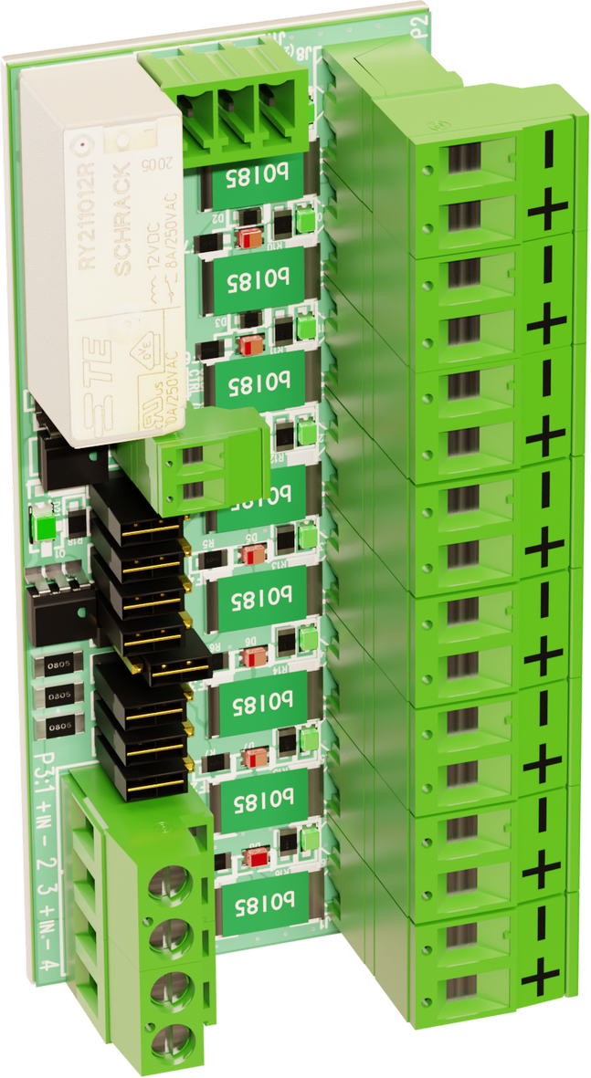
Fuse cards with eight outputs protected by PTC fuses. Protects electrical circuits against overcurrent and short Each output can be individually controllable/non-controllable via jumper.
Important
Maximum load per output is 1.85 A. All current for the whole board is max: 10 A.
What is a PTC fuse?
A PTC fuse, where "PTC" stands for "Positive Temperature Coefficient," is a type of thermal fuse or overcurrent protection device. These fuses are used to protect electrical circuits from overcurrent and short circuits.
Short description
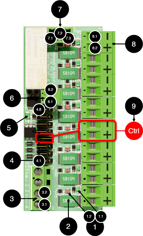
The board can be powered by 12 V or 24 V. The output voltage is always the same as the input voltage (12 V in = 12 V out, 24 V in = 24 V out).
No. | On Circuit Boards | Explanation |
|---|---|---|
1 | - | LED for status on PTC fuse. |
1.1 | D6-D9 | The LED lights up green in normal operation. |
1.2 | D1-D8 | LED lights up red when the fuse discharges and automatically turns off when the fuse returns to normal position. PTC Fuse Recovery. |
2 | F1-F8 | PTC fuse |
3 | P3 | Incoming supply voltage |
3.1 | P3:4 | - |
3.2 | P3:3 | + |
4, 4.1-4-8 | JU1-JU8 | Jumpers to select which output to prioritize. Example: if jumper JU4 is mounted on the two outer pins, it is controlled |
5 | D21 | LED lights up green when steering is active. |
6 | J9 | Connection for external (ctrl+) control of the board. |
6.1 | CTRL | CTRL connection should be connected to ground to enable control of outputs that are set as controlled. |
6.2 | (NC) | Ground, used for the CTRL connection when control is to be activated. |
7 | J11 | Inverts the control function. Contact support if you need this feature. |
7.1 | 24V (0V) | |
7.2 | - | |
7.3 | 0V (24V) | |
8 | P2 | Unload. |
8.1 | 8 Loading - | - out. |
8.2 | 8 Load+ | + out. |
9 (example, steering) | - | Example of control: To control output 4, jumper JU4 must be mounted on the outer two pins of the pin strip (see section 4.4). The output is then controlled via the CTRL connection |
Tip
CTRL: Controlling function, breaking function.
Jumpers
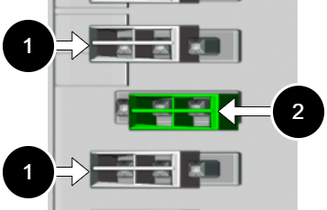
The jumpers should be mounted in one of the two positions on the three-row pin bar.
No. | Explanation | Function |
|---|---|---|
1 | Jumper on the outer pins. | Output active, without control. |
2 | Jumper on the inner pins. | Output is controlled using the CTRL signal. |
Caution
If jumper is missing on pins, there is no voltage on +, which causes the output to be off.
How governance works
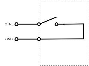
Basic function: The control input (CTRL) can be connected to an external switch or relay output to control selected outputs.
Configuration:
Select the outputs to be controllable by mounting jumpers (JU1-JU8, see section 4 of the PCB overview).
Connect CTRL and GND according to scheme.
Function | Explanation |
|---|---|
CTRL linked to GND (ground): | Controlled outputs are activated (voltage on the outputs). |
CTRL disconnected from GND: | Controlled outputs are disabled (no voltage on the outputs). |
Uncontrolled outputs (jumper on the internal pins) always have voltage. | |
Usage examples:
Priority load control in case of network outages.
Remote control of exits via fire alarm.
Time-controlled control via external timer.
Emergency shutdown of selected outputs.
Caution
For fire alarm applications: the card is not certified together with EN54 devices from Milleteknik.
Configuration of reverse control function
The behavior of the control function can be configured by modifying the conductor path.
If the conductor path is unchanged, voltage is given at the control signal.
If the guide path is scraped off, the function ceases; however, it can be restored by swapping 7.2-7.3. For reverse function jumper: 7.1 and 7.2
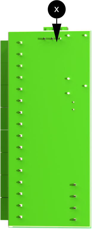
Instructions:
Scrape off the conductor path between 7.2 and 7.3, then use the terminal and jump 7.1 and 7.2 (or 7.2 and 7.3 for regular operation). The function can then be switched with an external switch
Tip
Use a scalpel. Avoid damaging adjacent paths.
Method | Guide path 7.2-7.3 | Jumper on the skirting board | Controlled outputs in normal mode (CTRL not active) |
|---|---|---|---|
Standard (from factory) | Whole | Not needed. | Tension of, (ending). |
Switchable function | Scratched | Jumpra 7.2-7.3 | Tension of, (ending). |
Switchable function | Scratched | Jumpra 7.1-7.2 | Tension on, (breaking). |
PTC Fuse Recovery
LED (1.2) lights up red when the fuse discharges and automatically turns off when the fuse returns to normal position. The fuse is restored by breaking the voltage on the load output by any of its actions:
Disconnect cargo.
For controlled output, the control signal can be used for reset.
For uncontrolled output: Break the supply voltage.
Mounting in battery backup
The card is delivered mounted in it's plastic casing, for easy installation.
Mount the card on any card slot in the enclosure, leave space for cables.
Important
Install the board before screwing on wiring or commissioning.
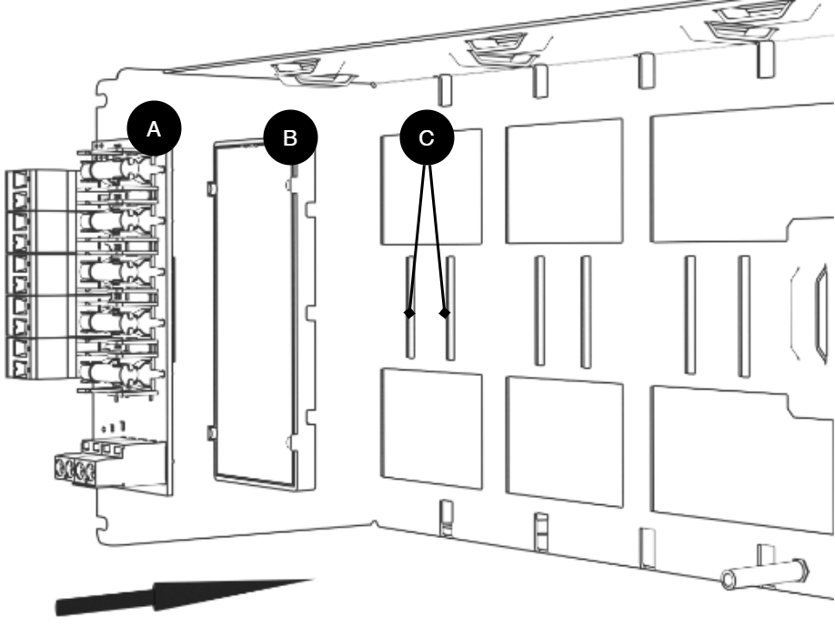
Letter | Explanation | Comment |
|---|---|---|
A | Optional card | Optional card comes mounted on plastic housing from factory. Has it come loose? Snap it back on before mounting the card. |
B | Plastic casing | The plastic casing has hooks for attaching slots in the plate. |
C | Place for plastic casing | Slits in sheet metal. |
Connect 8 Output module PTC to motherboard: CEO 3 v5
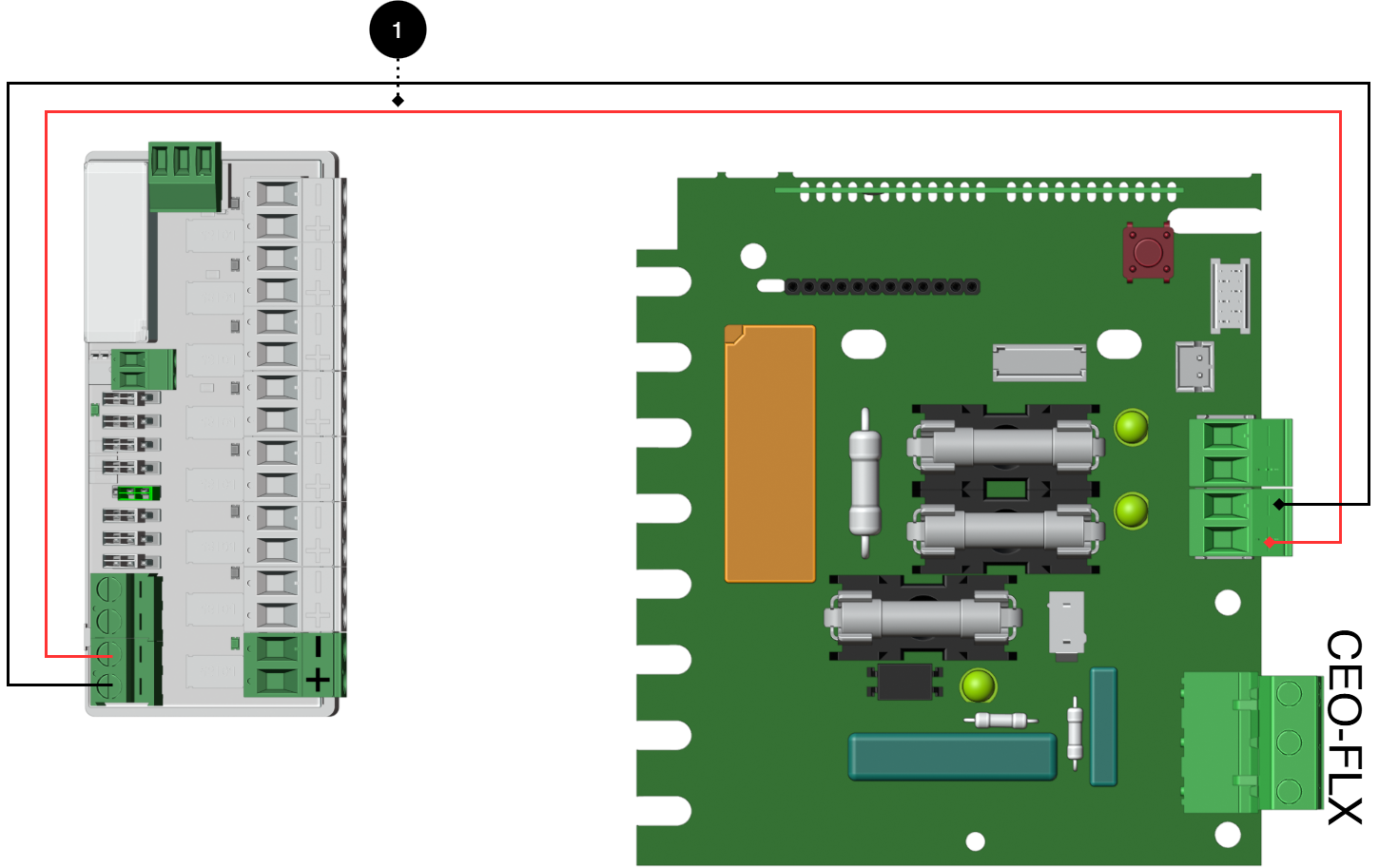
+ and - from load on motherboard are connected to + and - on the option board.
Connecting the power supply
Connect power (24 V) from the battery backup's load output to the card's 24 V input.
Connection of load
Connect load wiring to P2:1-8 on fuse module for priority load.
Important
Maximum load per output is 1.85 A. All current for the whole board is max: 10 A.
No | Connections | 8 Output module PTC CTRL | Motherboard |
|---|---|---|---|
1 | Power supply connection: | P1:1-4 | Optional load output |
Connect 8 Output module PTC to motherboard: CEO3 v 2.1
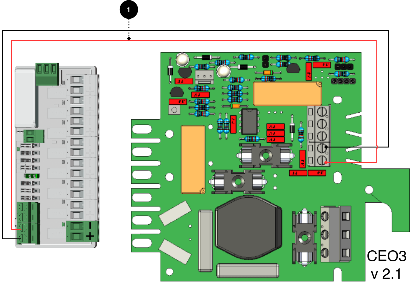
+ and - from load on motherboard are connected to + and - on the option board.
Connecting the power supply
Connect power (24 V) from the battery backup's load output to the card's 24 V input.
Connection of load
Connect load cable to P 2:1-8 on 8 Output module PTC CTRL.
Important
Maximum load per output is 1.85 A. All current for the whole board is max: 10 A.
No | Connections | 8 Output module PTC CTRL | Motherboard |
|---|---|---|---|
1 | Power supply connection | P1:1-4 | Optional load output. |
Connect 8 Output module PTC to motherboard: CEO 3 v5
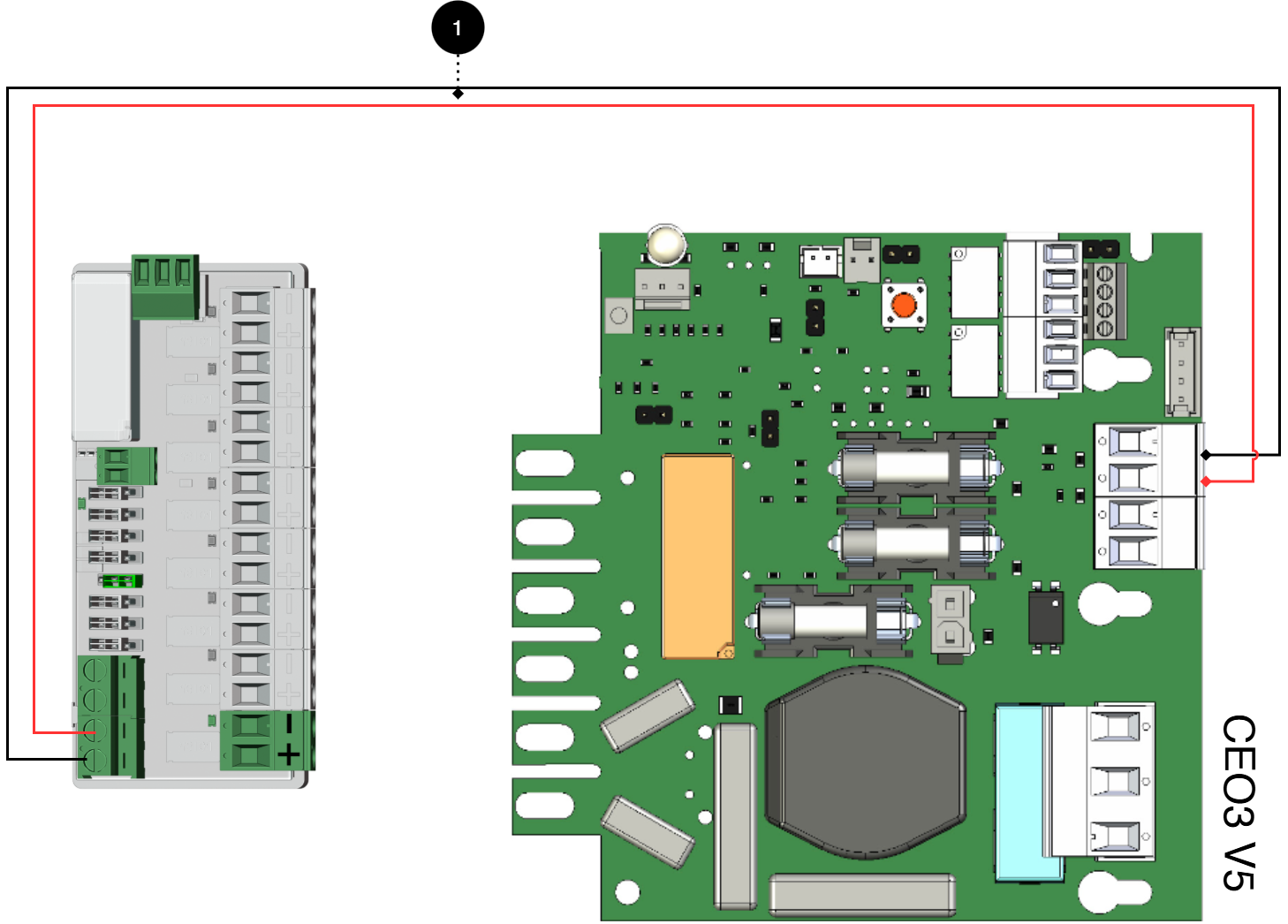
+ and - from load on motherboard are connected to + and - on the option board.
Connecting the power supply
Connect power (24 V) from the battery backup's load output to the card's 24 V input.
Connection of load
Connect load wiring to P2:1-8 on fuse module for priority load.
Important
Maximum load per output is 1.85 A. All current for the whole board is max: 10 A.
No | Connections | 8 Output module PTC CTRL | Motherboard |
|---|---|---|---|
1 | Power supply connection: | P1:1-4 | Optional load output |
Connect 8 Output module PTC to motherboard: PRO1, 15 A - 25 A
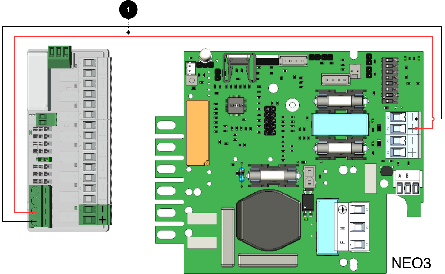
+ and - from load on motherboard are connected to + and - on the option board.
Connecting the power supply
Connect power (24 V) from the battery backup's load output to the card's 24 V input.
Connection of load
Connect load wiring to P2:1-8 on 8 Output module PTC.
Important
Maximum load per output is 1.85 A. All current for the whole board is max: 10 A.
No. | Couplings | 8 Output module PTC CTRL | Motherboard |
|---|---|---|---|
1 | Switching power supply: | P3:1-4 | Optional load output |
Connect 8 Output module PTC to motherboard: PRO1, 5 A - 10 A
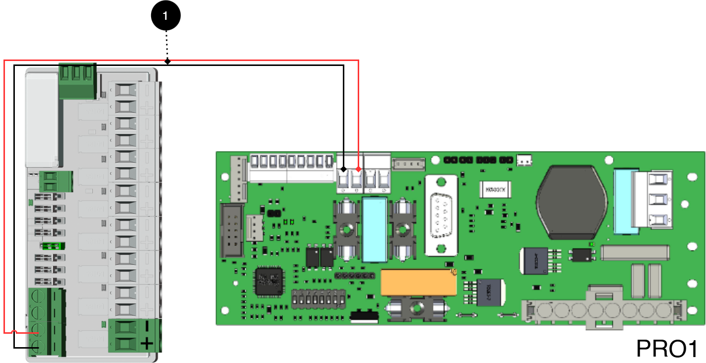
+ and - from load on motherboard are connected to + and - on the option board.
Connecting the power supply
Connect power (24 V) from the battery backup's load output to the card's 24 V input.
Connection of load
Connect load wiring to P2:1-8 on 8 Output module PTC.
Important
Maximum load per output is 1.85 A. All current for the whole board is max: 10 A.
No | Connections | 8 Output module PTC CTRL | Motherboard |
|---|---|---|---|
1 | Power supply connection: | P1:1-4 | Optional load output |
Connect 8 Output module PTC to motherboard: PRO1, 15 A - 25 A
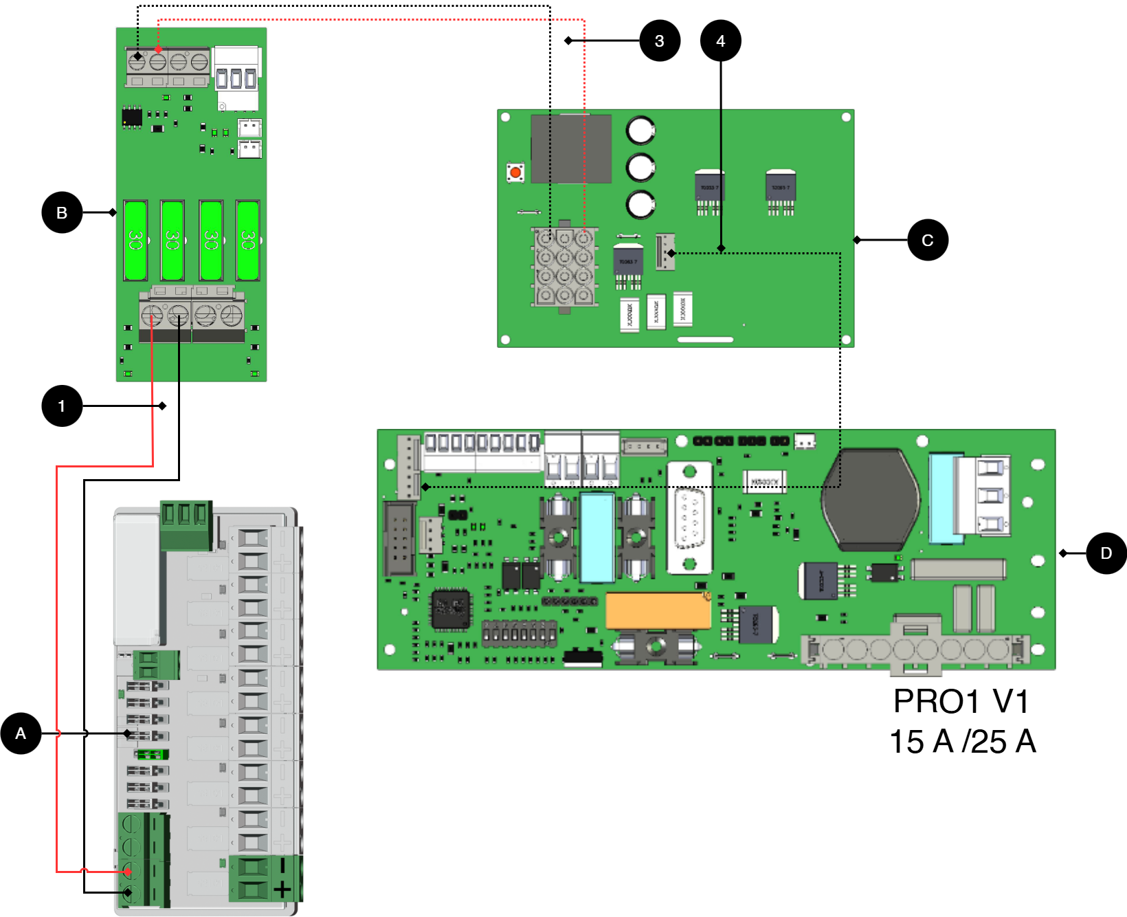
+ and - from load on motherboard are connected to + and - on the option board.
Connecting the power supply
Connect power (24 V) from the battery backup's load output to the card's 24 V input.
Connection of load
Connect load wiring to P2:1-8 on 8 Output module PTC.
Important
Maximum load per output is 1.85 A. All current for the whole board is max: 10 A.
No/letter | On circuit board (A) | Explanation |
|---|---|---|
A | 8 Output modules | Optional card. |
B | 2 Output module | Card for connection of load and power supply to 8 Outoput module PTC. |
C | Effect card | Available in 15 A and 25 A units. |
D | PRO1 | Motherboard in battery backup. |
1 | P1:1-4 | Connect power supply 8 Outoput module PTC from (B). |
3, 4, 5 | - | Internal power supply and communication between cards. |
Connect 8 Output module PTC to motherboard: PRO2 v3, 5 A - 10 A
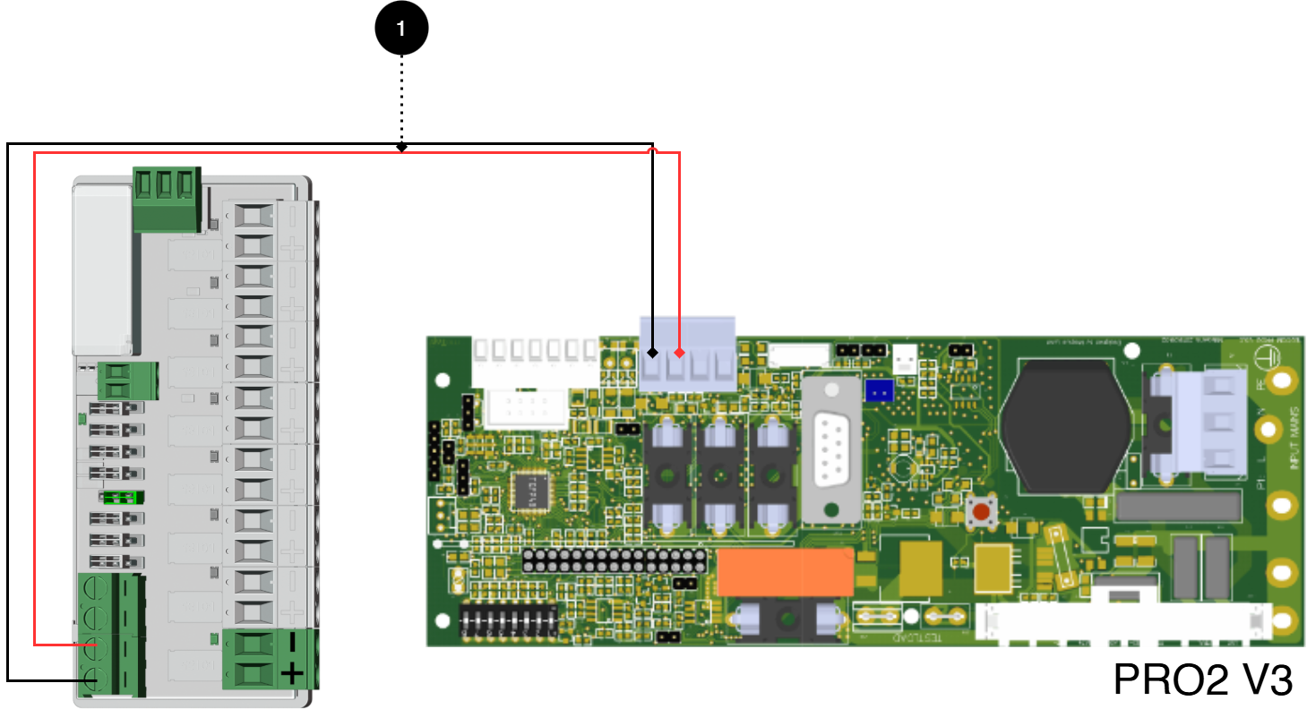
+ and - from load on motherboard are connected to + and - on the option board.
Connecting the power supply
Connect power (24 V) from the battery backup's load output to the card's 24 V input.
Connection of load
Connect load cable to P 2:1-8 on 8 Output module PTC CTRL.
Important
Maximum load per output is 1.85 A. All current for the whole board is max: 10 A.
No | Connections | 8 Output module PTC CTRL | Motherboard |
|---|---|---|---|
1 | Power supply connection: | P1:1-4 | Optional load output. |
Connect 8 Output module PTC to motherboard: PRO2 v3 15 A - 25 A
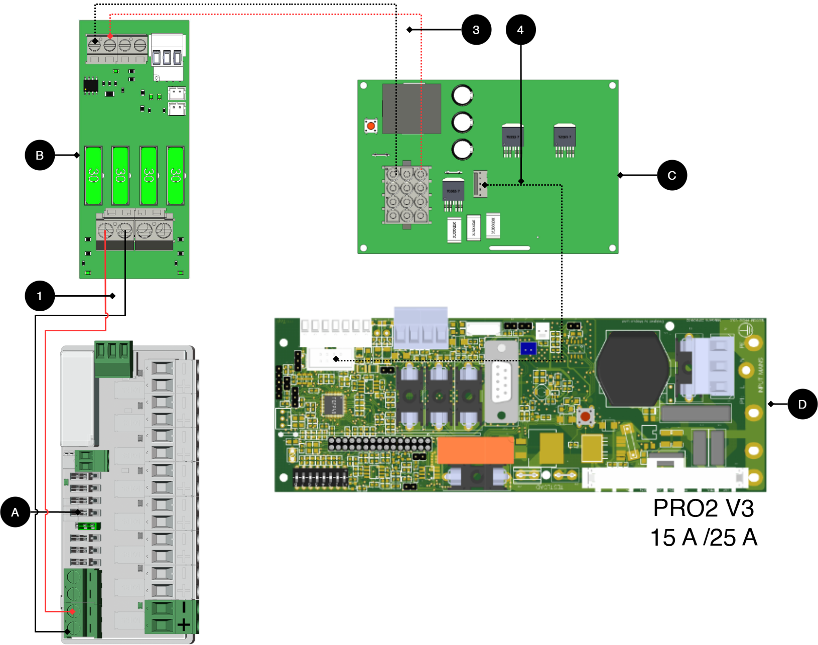
+ and - from load on motherboard are connected to + and - on the option board.
Connecting the power supply
Connect power (24 V) from the battery backup's load output to the card's 24 V input.
Connection of load
Connect load cable to P 2:1-8 on 8 Output module PTC CTRL.
Important
Maximum load per output is 1.85 A. All current for the whole board is max: 10 A.
No/letter | On circuit board (A) | Explanation |
|---|---|---|
A | 8 Output module PTC CTRL | Optional location. |
B | 2 Output module | Card for connection of load and power supply to 8 Outoput module PTC. |
C | Effect card | Available in 15 A and 25 A units. |
D | PRO2 v3 | Motherboard in battery backup. |
1 | P1:1-4 | Disconnect power supply 8 Outoput module PTC (B). |
3, 4 | - | Internal power supply and communication between cards. |
Connect 8 Output module PTC to motherboard: PRO3 5 A - 10 A
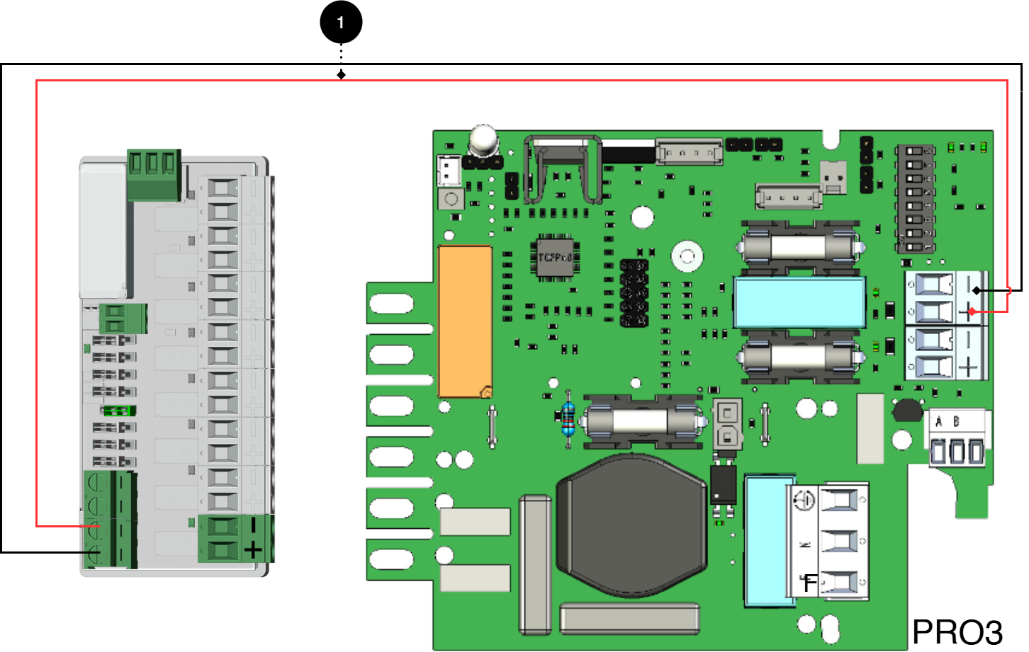
+ and - from load on motherboard are connected to + and - on the option board.
Connecting the power supply
Connect power (24 V) from the battery backup's load output to the card's 24 V input.
Connection of load
Connect load cable to P 2:1-8 on 8 Output module PTC CTRL.
Important
Maximum load per output is 1.85 A. All current for the whole board is max: 10 A.
No | Connections | 8 Output module PTC CTRL | Motherboard |
|---|---|---|---|
1 | Power supply connection: | P3:1-4 | Optional load output. |
Connection of another 8 outout module PTC
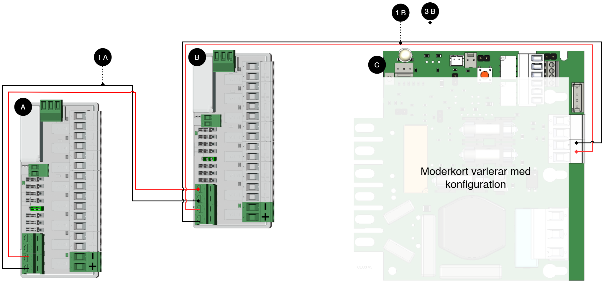
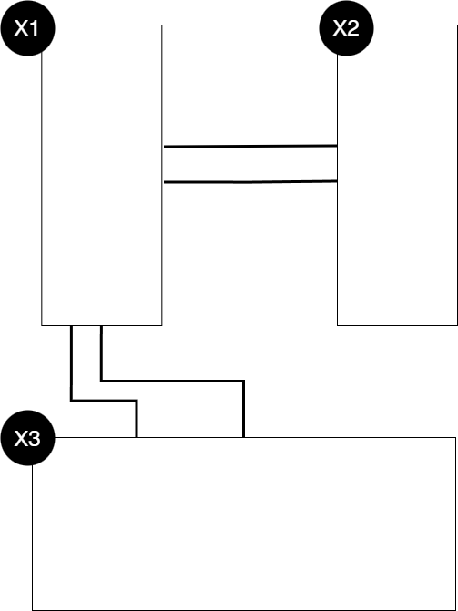
Letter / No | Explanation | On the card |
|---|---|---|
A | 8 Output module PTC CTRL. | - |
B | 8 Output module PTC CTRL. | - |
C | Motherboard, may vary with configuration. | - |
1 A | Power supply to 1B from 1A. | P1:1-+2 |
1 B | Power supply to 1B from motherboard. | P1:3-4 |
Letter / No | Explanation |
|---|---|
X1 | Optional card 1 |
X2 | Optional card 2 |
X3 | Motherboard |
Product sheet - power supply / battery backup
Product Sheet
Product image
Item Information
The table shows the name, part number and email number of the product
Product Identification
Product designation | Item No. | E-number (SE) (sv) |
|---|---|---|
8 Output module PTC CTRL | A-FU122408OP03LM01 | 52 137 79 |
Technical description
Cancellation card with eight thermally protected outputs. The board protects electrical circuits with PTC fuses that automatically break the current in case of overload and reset when the overload ceases. Each output can be individually controlled via jumper. The card works with both 12 V DC and 24 V DC.
Quick Facts | |||||||||||||||||||||||||||||||||||||||||||||||||
|---|---|---|---|---|---|---|---|---|---|---|---|---|---|---|---|---|---|---|---|---|---|---|---|---|---|---|---|---|---|---|---|---|---|---|---|---|---|---|---|---|---|---|---|---|---|---|---|---|---|
Supply voltage (V) | 27.3 V DC (24 V DC) or 13.6 V DC (12 V DC) | ||||||||||||||||||||||||||||||||||||||||||||||||
Voltage out (V) | 27.3 V DC (24 V DC) or 13.6 V DC (12 V DC)[a] | ||||||||||||||||||||||||||||||||||||||||||||||||
Current output (A), max load current output. | 1.85 A per output[b] | ||||||||||||||||||||||||||||||||||||||||||||||||
Accessories for | Outdoor Enclosures. | ||||||||||||||||||||||||||||||||||||||||||||||||
[a] The device is not equipped with any DC/DC converter. The output voltage therefore corresponds to the input [b] Holding current 2.7 A | |||||||||||||||||||||||||||||||||||||||||||||||||
Areas of application
Areas of application | Yes | No |
|---|---|---|
When additional cargo outputs are needed. Mounts in compatible power supply | ✔ | |
Ability to turn off unprotected load in case of network outage. | ✔ |
Electrical data
Electrical data | |||||||||||||||||||||||||||||||||||||||||||||||||
|---|---|---|---|---|---|---|---|---|---|---|---|---|---|---|---|---|---|---|---|---|---|---|---|---|---|---|---|---|---|---|---|---|---|---|---|---|---|---|---|---|---|---|---|---|---|---|---|---|---|
Supply voltage | 27.3 V DC (24 V DC) or 13.6 V DC (12 V DC) | ||||||||||||||||||||||||||||||||||||||||||||||||
Standby consumption | 0.48 W, 0.96 W if CTRL is active. | ||||||||||||||||||||||||||||||||||||||||||||||||
Voltage out | 27.3 V DC (24 V DC) or 13.6 V DC (12 V DC)[a] | ||||||||||||||||||||||||||||||||||||||||||||||||
Current (A)[b] | 1.85 A per output[c] | ||||||||||||||||||||||||||||||||||||||||||||||||
Input control | Input drive voltage, (12 V) | ||||||||||||||||||||||||||||||||||||||||||||||||
Max current, full board | 10A | ||||||||||||||||||||||||||||||||||||||||||||||||
[a] The device is not equipped with any DC/DC converter. The output voltage therefore corresponds to the input [b] Power outlet/load is specified as max, normal current output should be 80% of max. [c] Holding current 2.7 A | |||||||||||||||||||||||||||||||||||||||||||||||||
Fuses | |
|---|---|
Electronic load securing (PTC) | PTC discharges at about 3.4 A |
Circuit Boards | Internal power consumption | Other. info |
|---|---|---|
8 Output module PTC CTRL | 20 mA | 40 mA with CTRL active. |
Load outputs
Load outputs | |
|---|---|
Number of load outputs | ! 8 |
Alarm and protection
Alarms | Yes | No |
|---|---|---|
Switching Relay | ✔ Supply voltage output at control signal. |
Alarm and protection | Yes | No |
|---|---|---|
Overload Protection/Surge Protection | ✔ |
Communication and Indications
Communication and Indications | Yes | No | Other. info. |
|---|---|---|---|
Communication | ✘ | ||
Alarm feedback to power supply | ✔ | ||
Indicators/LEDs | ✔ | LED on circuit board. |
Enclosure and Mechanics
Enclosure and Mechanics | |
|---|---|
Type | Printed circuit board, product does not have enclosure |
Assembly, installation and eligibility requirements
Fitting | Yes | No |
|---|---|---|
In product (optionally fitted in compatible product). | ✔ |
Installation | Yes | No |
|---|---|---|
Installed in product. | ✔ |
Dimensions, weight and packaging information
Net weight | Weight with packaging |
|---|---|
0.1 kg | 0.2 kg |
Packaging | |
|---|---|
Packaging | Cardboard and impact protection in cardboard. |
Quantity in pack | 1 pc. |
Packaging Type (GS1 T0137) | BX box. |
Conditions EUR pallet | EUR pallets may not be stacked during transport or storage. Stacking may result in damage to product and packaging |
Transport environment | The product must be protected from condensation and direct precipitation during transportation. |
Transport temperature (without battery) | −30 °C to +70 °C |
Storage environment | Dry indoor environment, protected from condensation. Relative humidity: max 95%, non-condensing |
Storage temperature without batteries | −20 °C to +60 °C |
The accessories fits in
Contact
Department | |
|---|---|
Switchboard | 031-340 02 30 |
Support and technical issues | support@milleteknik.se |
Sales | sales@milleteknik.se |
WWW | www.milleteknik.se |
Address | Ögärdesvägen 8B, 433 30 Partille |
About this information
All information is published subject to possible errors. Information is updated without prior notice. |
Publication date 2026-07-09
Compliance and regulatory compliance
Delivery time, warranty and terms
Delivery time, warranty and terms | |||||||||||||||||||||||||||||||||||||||||||||||||
|---|---|---|---|---|---|---|---|---|---|---|---|---|---|---|---|---|---|---|---|---|---|---|---|---|---|---|---|---|---|---|---|---|---|---|---|---|---|---|---|---|---|---|---|---|---|---|---|---|---|
Warranty period[a] | The product has a two (2) year warranty against manufacturing defects. | ||||||||||||||||||||||||||||||||||||||||||||||||
Special warranty conditions | See also general terms and conditions. | ||||||||||||||||||||||||||||||||||||||||||||||||
General Terms and Conditions | ALEM09 with exceptions, see: www.milleteknik.se/conditions/ | ||||||||||||||||||||||||||||||||||||||||||||||||
Support | Telephone support and email support during the warranty period are free of charge. For spare parts that are not covered by warranty, there is a charge | ||||||||||||||||||||||||||||||||||||||||||||||||
Delivery and stock | |||||||||||||||||||||||||||||||||||||||||||||||||
Delivery time[b] | 3 working days. Or as per agreement. Delivery from factory, transportation time is added. | ||||||||||||||||||||||||||||||||||||||||||||||||
[a] If the device is purchased through a wholesaler or other supplier, other warranty conditions may apply. [b] In the case of larger orders, delivery time increases, acc. to agreement. | |||||||||||||||||||||||||||||||||||||||||||||||||
Operation and maintenance
Operation | Data | Other. info | |||||||||||||||||||||||||||||||||||||||||||||||
|---|---|---|---|---|---|---|---|---|---|---|---|---|---|---|---|---|---|---|---|---|---|---|---|---|---|---|---|---|---|---|---|---|---|---|---|---|---|---|---|---|---|---|---|---|---|---|---|---|---|
Environment | Indoor environmental class 1. | ||||||||||||||||||||||||||||||||||||||||||||||||
Operating temperature (recommended) | +15°C to +25°C | ||||||||||||||||||||||||||||||||||||||||||||||||
Operating temperature (permissible)[a] | +5°C to +40°C | Class 1 according to EN 50131-6/ EN 60839-11 | |||||||||||||||||||||||||||||||||||||||||||||||
[a] Specifies the permissible ambient temperature range in which the product can operate without damage. See also table on battery life. | |||||||||||||||||||||||||||||||||||||||||||||||||
Yes | No | Interval | Other. info |
|---|---|---|---|
✔ | Maintenance-free. |
Certifications and approvals
Complies with | Directives |
|---|---|
C.E. | CE marking according to Regulation (EC) No 765/2008 |
RoHS | RoHS Directive 2011/65/EU, including amendment (EU) 2015/863 |
EMC | EMC Directive 2014/30/EU |
Electric (LVD) | Low Voltage Directive 2014/35/EU |
Environmental data
Environmental data | J/N | Informație | Other. info. | ||||||||||||||||||||||||||||||||||||||||||||||
|---|---|---|---|---|---|---|---|---|---|---|---|---|---|---|---|---|---|---|---|---|---|---|---|---|---|---|---|---|---|---|---|---|---|---|---|---|---|---|---|---|---|---|---|---|---|---|---|---|---|
Building Product Declaration (BPD) | ✔ | Yes, see iBvd at www.milleteknik.se. | - | ||||||||||||||||||||||||||||||||||||||||||||||
REACH Information Obligation (EC) No 1907/2006 | ✔ | Yes, see the DoC at www.milleteknik.se The product complies with REACH Regulation (EC) No 1907/2006. | If empty, the product is not covered. | ||||||||||||||||||||||||||||||||||||||||||||||
SVHC substances, CAS/EC | ✔ | Yes, lead, 7439-92-1/231-100-4 | For text, see iBvd at www.milleteknik.se. If blank, substance is missing. | ||||||||||||||||||||||||||||||||||||||||||||||
Subject to the RoHS Directive, (EU) 2015/863) | ✔ | Yes, see the DoC at www.milleteknik.se | |||||||||||||||||||||||||||||||||||||||||||||||
WEEE 2012/19/EU | ✔ | The product contains electrical components or wiring and is covered by the WEEE Directive (2012/19/EU). | If empty, the product is not covered. End-of-life products must be returned to a recycling centre | ||||||||||||||||||||||||||||||||||||||||||||||
Battery Regulation (EU) 2023/1542 | ✗ | ||||||||||||||||||||||||||||||||||||||||||||||||
SCIP No 2008/98/EC | ✔ | Yes, registered under the EU Waste Directive where applicable, (2008/98/EC). | If empty, no SCIP number is needed. | ||||||||||||||||||||||||||||||||||||||||||||||
Conflict minerals (EU) 2017/821 | ✗/✗/✗/✗/✔ | No=Gold, Tungsten, Tantalum, Cobalt. Yes=Tin | Tin in solders in printed circuit boards purchased through a Swedish supplier. | ||||||||||||||||||||||||||||||||||||||||||||||
Contains nanomaterials: EC 1272/2008 | ✗ | The product does not contain nanomaterials. | |||||||||||||||||||||||||||||||||||||||||||||||
Ecodesign 2009/125/EC | Milleteknik's products are intended for professional use and are therefore not directly covered by the Ecodesign Regulation (EU 2019/1782). As some components may be covered, we nevertheless disclose relevant information[a], where applicable, to provide our customers with confidence in their choice. | ||||||||||||||||||||||||||||||||||||||||||||||||
Machine Directive 2006/42/EC | The product is part of electrical systems, is subject to the relevant electrical and safety directives and is not a machine according to the Machinery Directive (2006/42/EC). Will be replaced by Machinery Regulation (EU) 2023/1230, which will apply in 2027. | ||||||||||||||||||||||||||||||||||||||||||||||||
The product is designed for a long service life, which reduces the environmental impact. End-of-life products are handed over to the nearest recycling centre. | |||||||||||||||||||||||||||||||||||||||||||||||||
[a] Standby consumption and power. | |||||||||||||||||||||||||||||||||||||||||||||||||


Manufacturer and country of origin
Manufacturer[a] | Milleteknik AB | ||||||||||||||||||||||||||||||||||||||||||||||||
Customs State. Nos. | 85044095[b] | ||||||||||||||||||||||||||||||||||||||||||||||||
Country of origin | Sweden | ||||||||||||||||||||||||||||||||||||||||||||||||
[a] Manufacturer is the trademark indicated on the product, regardless of what is stated in this product sheet. [b] Verify with the Customs Ombud/Customs Service for export/import; alternative classification 85044055 may become applicable if the product is assessed as a battery charger. | |||||||||||||||||||||||||||||||||||||||||||||||||
Appendix
Eligibility requirements, installation
Eligibility requirements vary between countries. The table summarizes national requirements for fixed installation and connection of equipment with a plug socket, respectively.
Options on the secondary side of the product, such as 12 V, 24 V or 48 V DC, are connected according to the respective instructions. Work on the network connection of the product shall be carried out in accordance with national eligibility requirements
Permission Requirements for Installation | Fixed installation (230 V) | Plug | Other. info |
|---|---|---|---|
Sweden | ✔ | ✗ | Fixed installation may be performed by technicians but shall be under the responsibility of a qualified installer. (Electrical Safety Act, SS 436 40 00) Plug may be connected without authorization. |
Norway | ✔ | ✔ | Requirements for qualified electricians also for equipment with a plug socket in fixed installations. (NEK 400, DSB |
Finland | ✔ | ✗ | Plug may be connected without authorization. (Tukes, SFS 6000 |
Denmark | ✔ | ✗ | Plug may be connected without authorization. (Safety Board |
Germany | ✔ | ✗ | All fixed installations require a qualified electrician according to VDE 0100. Plug sockets may be connected without authorization, but only by person with basic electrical knowledge (“Elektrotechnisch unterwiesene Person”) |
Reference table: environmental classes according to EN 50130-5 (referred to in EN 50131-6)
Class | Type | Temperature range |
|---|---|---|
Environmental Class 1 | Heated indoors (type office/residence). | +5°C to +40°C |
Environmental Class 2 | Generally indoors (type warehouses/stairwells, not temperature controlled). | -10°C to +40°C |
Environmental class 3 | Protected outdoors. | -25°C to +50°C |
Environmental class 4 | Generally outdoors. | -25°C to +60°C |
About this information
All information is published subject to possible errors. Information is updated without prior notice. |
Publication date 2026-07-09