
If
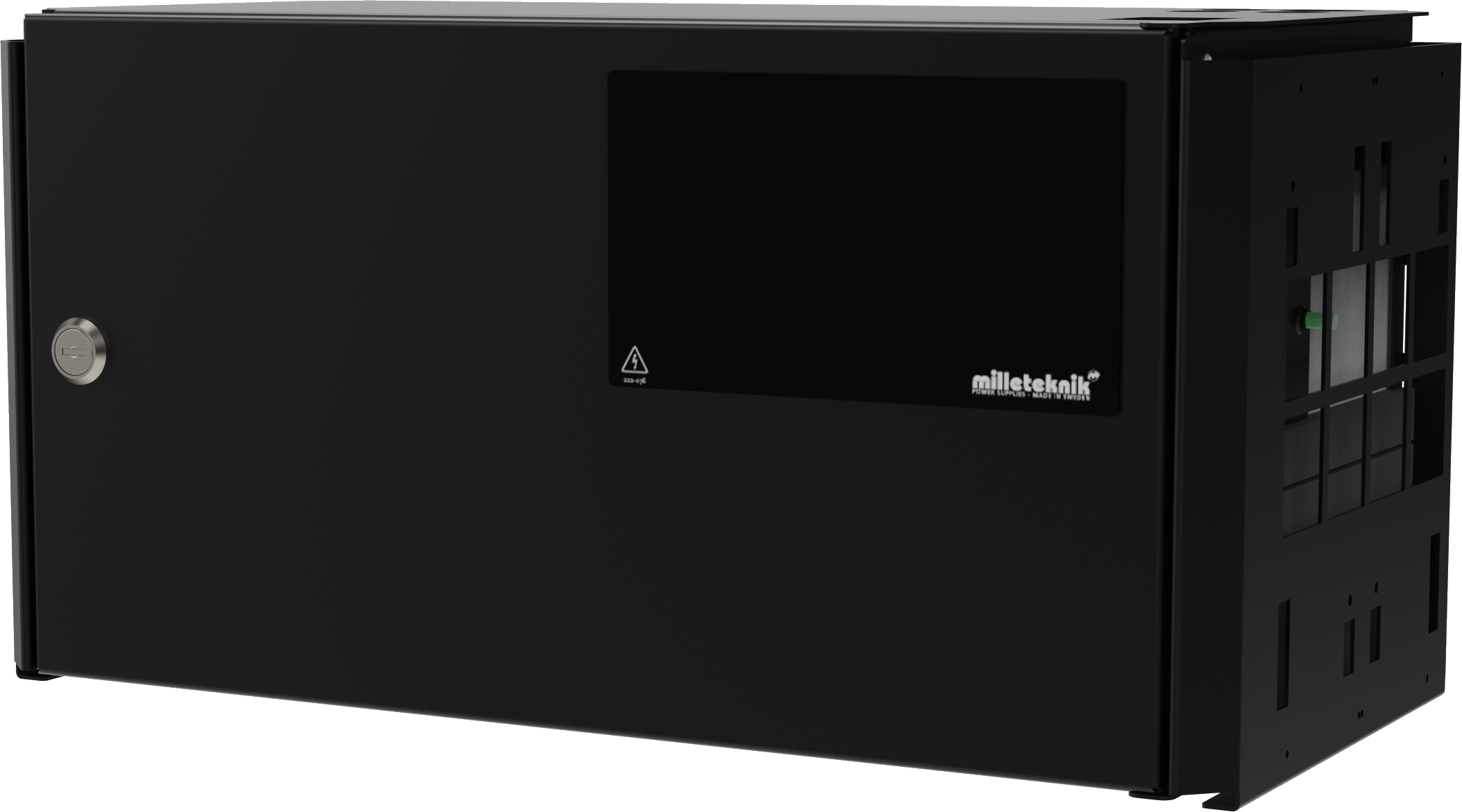
FLX M housing with insert for accessories for Sentrion S4.
Installation and commissioning
Instructions for installation and commissioning.
Product image
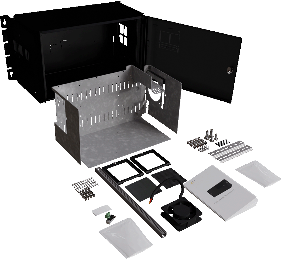
Product Identification
Product designation | Item No. | E-number (SE) (sv) |
|---|---|---|
FLX M Cassette for Sentrion S4 | FM010000000FLX01 | 52 137 15 |
What comes with it?
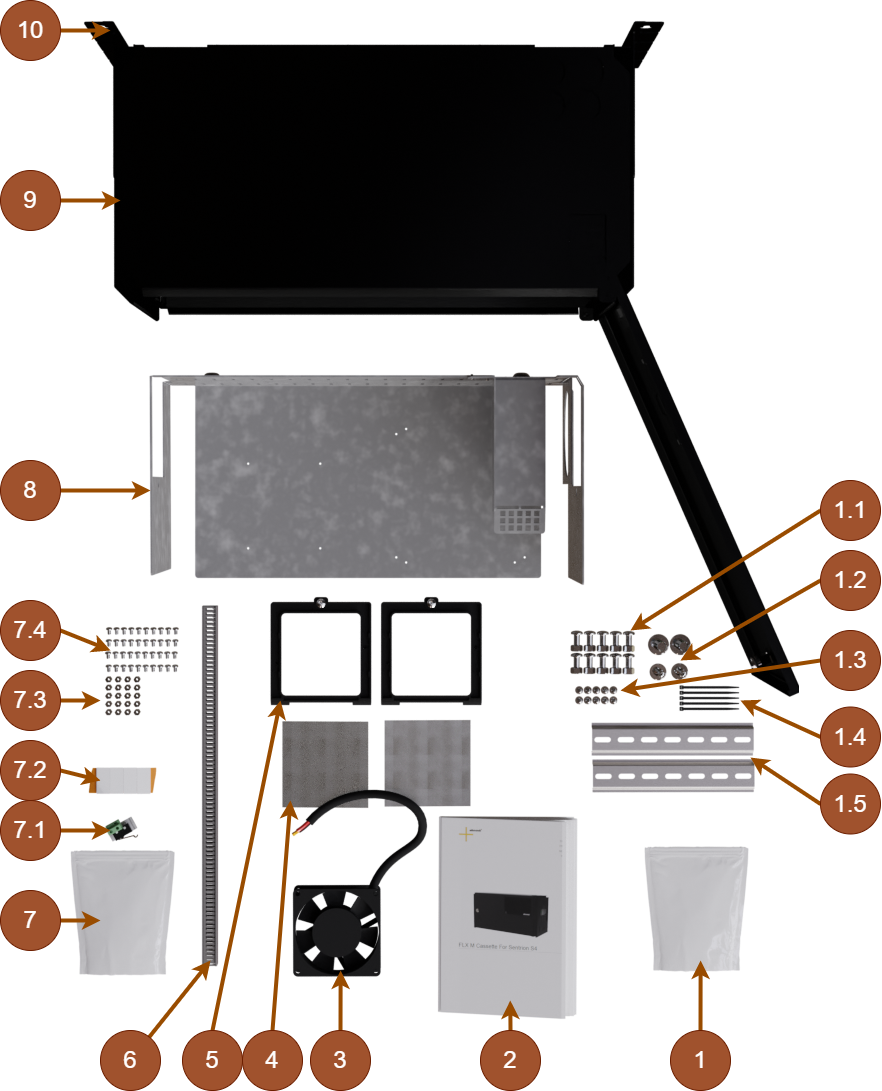
No | Explanation |
|---|---|
1 | Pouch. |
1.1 | 10 pieces of screw, M5x6 and lock nut, M5. |
1.2 | Two screws, M5x16 and two screws, M5x6. |
1.3 | Ten screw, 2.9 mm. |
1.4 | Five cable ties, 9 mm. |
1.5 | Two DIN rails, 190 mm. |
2 | User manual in Swedish. |
3 | Fan, 24 V. |
4 | Ventilation grille. |
5 | Holder for ventilation grilles. |
6 | Cable channel, 400 mm. |
7 | Pouch. |
7.1 | Tamper switch, 12 V or 24 V. |
7.2 | Four attachment pads. |
7.3 | 20 spacers, M3, 10 mm. |
7.4 | 40 pieces TT screw M3x6. |
8 | Plate insert. |
9 | FLX M tin box. |
10 | Bracket for wall or 19" rack. |
Overview configurations
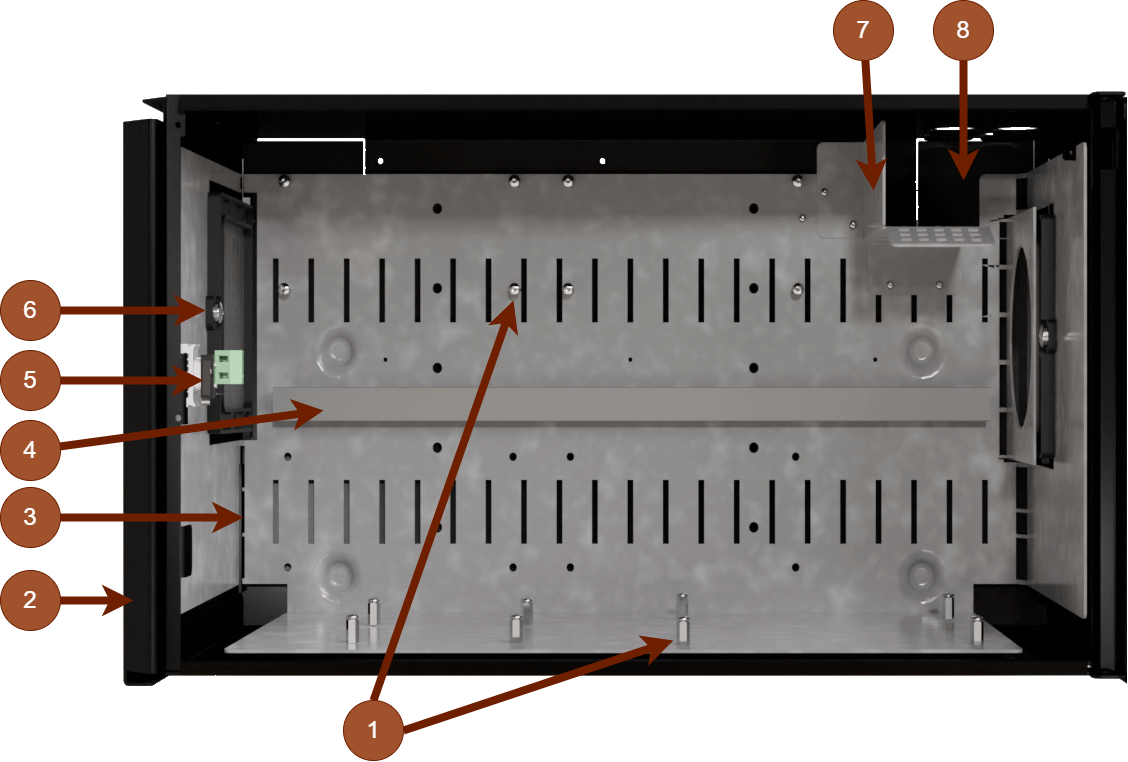
Image of how components can be assembled.
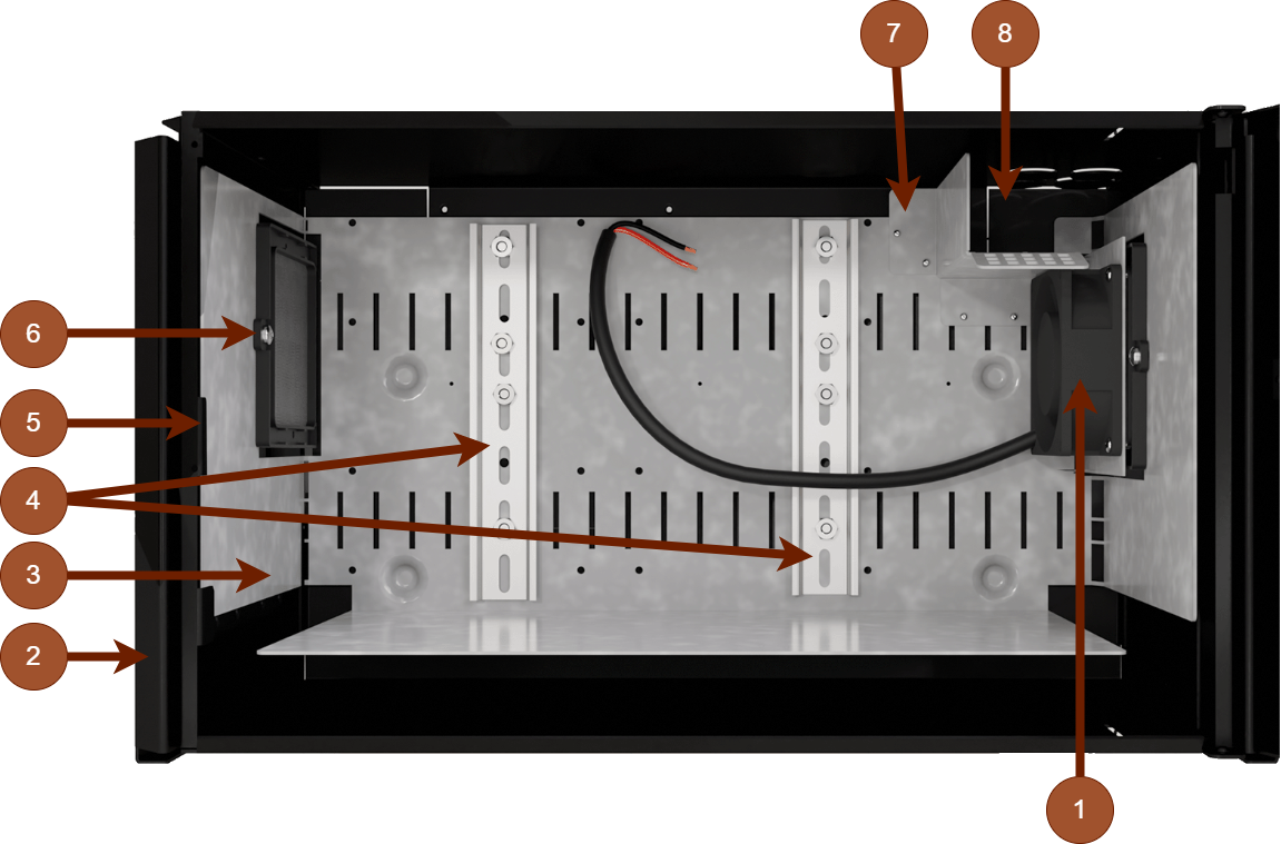
Image of how components can be assembled.
No | Explanation Both configurations | Explanation configuration 1 | Explanation configuration 2 |
|---|---|---|---|
1 | - | Distances. | Fan. |
2 | Enclosure. | ||
3 | Cassette plate. | ||
4 | - | Cable channel. | DIN rails. |
5 | Tamper contact, place for. | ||
6 | Ventilation grille. | ||
7 | Sheet metal cable channel. | ||
8 | Cable entries. | ||
Install the supplied components
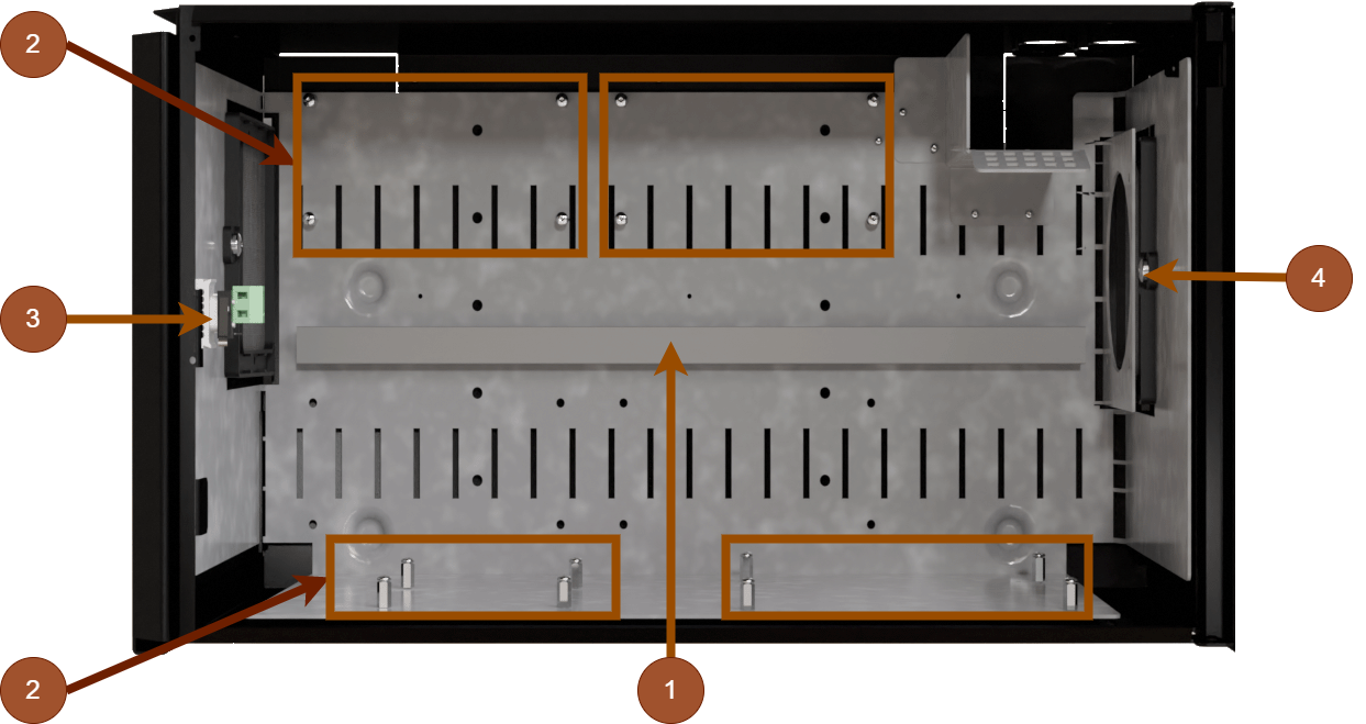
No | Explanation |
|---|---|
1 | Cable channel is screwed into sheet metal. |
2 | Mount spacers and screw on plate. Distances are screwed from both sides. Use two screws per spacer. |
3 | The tamper contact is pressed onto a sheet tongue in the enclosure. |
4 | Ventilation grilles are placed in holders and screwed into sheet metal. |
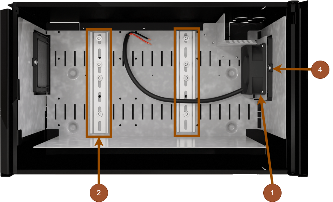
No | Explanation |
|---|---|
1 | Fan is screwed with four sheet metal screws. |
2 | Mount DIN rails with four screws and nuts in each DIN rail. |
3 | - |
4 | Ventilation grilles are placed in holders and screwed into sheet metal. |
Enclosures
General assembly instructions
Mounting - wall mounting
Enclosure must be mounted vertically.
For good ventilation, at least 100 mm of free space should be provided above and on the sides of the enclosure. Do not block the flow of air on the sides
The device should be mounted at a comfortable working height, normally between 1.4 and 1.8 m.
Recommended distance between screw head and wall should be 1.5-2 mm.
Avoid placement in direct sunlight, near heat sources, or in environments with high humidity or dust.
Installation shall be carried out in accordance with the applicable installation rules and by a competent installer.
Indoor mounting in 19" rack
The product should be mounted in a standardized 19" rack or cabinet with sufficient carrying capacity for the weight of the enclosure including batteries.
The device should be mounted at a comfortable working height, normally between 1.4 and 1.8 m.
The device is mounted horizontally in the rack with the included rack ears or corresponding brackets.
Check that the rack posts are properly aligned and that the spacing corresponds to the 19" standard (465—470 mm between the inner edge of the posts).
Use at least two mounting points (on each side) on the rack ears for stable attachment. Recommended screw size is M5 or M6
When assembling, cage nuts or locking washers should be used to ensure that the screws fit securely.
For good ventilation, at least 100 mm of free space should be provided above and below the unit. Do not block the air flow on the front or back.
Batteries should always be placed as directed and must not block ventilation openings or wiring.
Installation shall be carried out in accordance with the applicable installation rules and by a competent installer.
Mounting
Use the appropriate screw for mounting on a wall or in a 19" rack. Screws for mounting on a wall or in a rack are not included.
For wall mounting in concrete, concrete screws must be used. For rack mounting, M6 with basket nut is used
Screw length should be adjusted according to wall material and load. The specified screw length is the minimum allowable length
Bracket
The supplied brackets can be attached in two ways: When mounting on a wall, the brackets must sit backwards, against the wall. When mounting in a 19" rack, the bracket must sit at the front of the unit.
Letter | Explanation |
|---|---|
A | Bracket is pushed in from the bottom up. |
B | Clip clicks in when bracket is pushed in correctly. |
Product data sheet
Product Sheet
Product image
Product Identification
Product designation | Item No. | E-number (SE) (sv) |
|---|---|---|
FLX M Cassette for Sentrion S4 | FM010000000FLX01 | 52 137 15 |
Designation
Accessory box for Sentrion S4
Area of use
To install accessories for the Sentrion S4 in its own enclosure.
Technical description
Box with insert for attaching accessories to DIN rail or insert.
Enclosure
Weight
Name | Net weight | Weight incl. packaging |
|---|---|---|
FLX M Cassette for Sentrion S4 | 7.35 kg | 8.25 kg |
Installation requirements
The device is intended for fixed installation. The unit must be installed indoors, environmental class 1, ambient temperature: +5°C to +40°C. Recommended ambient temperature is +15°C to +25°C (for optimal battery life).
Requirements that the product meets
CE marking: | Regulation (EC) No 765/2008 |
Environment | REACH: The product complies with REACH Regulation (EC) No 1907/2006. RoHS Directive 2011/65/EU, including amendment (EU) 2015/863 SCIP: registered under the EU Waste Directive where applicable, (2008/98/EC). WEEE: The product contains electrical components or wiring and is covered by the WEEE Directive (2012/19/EU). End-of-life products must be returned to a recycling centre Batteries: If the product is supplied with batteries, it is covered by the Battery Regulation (2023/1542). Expired batteries must be removed from the product and returned to a recycling centre |
Machinery Directive | The product is part of electrical systems, is subject to the relevant electrical and safety directives and is not a machine according to the Machinery Directive (2006/42/EC). |
Ecodesign | Milleteknik's products are intended for professional use and are therefore not directly covered by the Ecodesign Regulation (EU 2019/1782). As some components may be covered, we nevertheless disclose relevant information to give our customers confidence in their choice |
Denomination | Efficiency (%)[a] | Standby consumption, typical (W): | |||||||||||||||||||||||||||||||||||||||||||||||
|---|---|---|---|---|---|---|---|---|---|---|---|---|---|---|---|---|---|---|---|---|---|---|---|---|---|---|---|---|---|---|---|---|---|---|---|---|---|---|---|---|---|---|---|---|---|---|---|---|---|
1. Accessories, expansion or optional cards that do not convert energy themselves, but only control, monitor or distribute it, do not fall under the Ecodesign Directive | |||||||||||||||||||||||||||||||||||||||||||||||||
-! 1 | - | ||||||||||||||||||||||||||||||||||||||||||||||||
[a] At rated load. | |||||||||||||||||||||||||||||||||||||||||||||||||


Limitations
As the unit's details are not assembled, it is the installer's responsibility that these and components are assembled safely and correctly. If 230 V is drawn into the product, the components, plate and door must be earthed.
Guarantee
Manufacturing, lifespan, environmental impact and recycling
Manufactured by Milleteknik in Partille, Sweden.
Link to the latest information
Products and software are subject to updates, you will always find the latest information on our website.
About this information
All information is published subject to possible errors. Information is updated without prior notice. |
Publication date 2026-07-13