
Before you begin
Information
Read this first!
Electronics, regardless of enclosure, are intended for use in a controlled indoor environment. Mains voltage should be disconnected during installation.
It is the installer's responsibility that the system is suitable for its intended use. Only authorized persons should install and maintain the system.
All information subject to change.
Support
Do you need help with installation or connection? Scan the QR code to read the entire manual.
You will find answers to many questions at: www.milleteknik.se go to your product to read more, download manuals and other product information.
Telephone: +46 31- 340 02 30, e-mail: support@milleteknik.se.
Support is open: Monday-Thursday 08:00-16:00, Fridays 08:00-15:00. Closed 11:30-13:15.
Link to the latest information
Products and software are subject to updates, you will always find the latest information on our website.
Link to technical specifications
Help us make better products
With your help we can develop and produce better products, please fill in our form customer satisfaction survey.
Installation and commissioning
Instructions for installation and commissioning.
About PoE from Milleteknik
The series is designed to power PoE devices such as access systems, surveillance cameras and other equipment that can be operated with Power over Ethernet.
PoE M-switch 4p FLX M, PoE M-switch 8p FLX M and PoE M-Switch 16p FLX M meet 802.3at type2 class 4. The PoE switch is managed, i.e. it is possible to control the switch via its software interface. The products have something we call "controlled charging", which is a safety function that means that batteries are not charged with more than 4.5 A. By controlling the charging of batteries, the lifespan of batteries is significantly extended. The product has 24 V battery voltage which is boosted up to 48 V to power the PoE switch. There is a load output on the motherboard that provides 24V, this allows the device to be used to power other applications such as door locks, etc on the one load output. It is important to accurately calculate the load so that the unit's specifications are not exceeded. Battery box can be connected for extended backup drive time.
PoE powers devices connected to the power supply
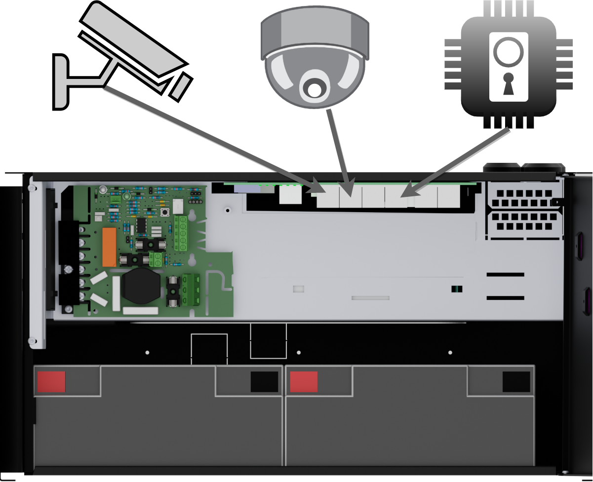 |
PoE can power, for example, surveillance cameras.
Connect external devices to be powered via PoE in PoE ports.
Connect other devices that do not need to be power supplied in LAN ports.
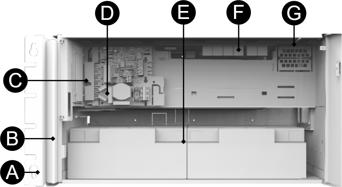
Component overview PoE FLX M
Symbol | Explanation |
|---|---|
A | Brackets, reversible. |
B | Casing in powder-coated sheet metal. |
C | Power supply, (placed under the motherboard). |
D | Motherboard. |
E | Room for batteries. |
F | Eight PoE ports are clustered together and two LAN ports are clustered together. |
G | Cable entries. |
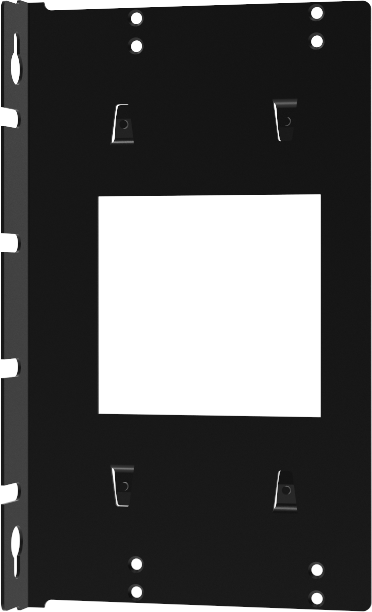
Bracket for FLX M and FLX L
Bracket is reversible and can be mounted in two ways. It comes with brackets in to the device.
 |
Batteries - placement and connection
Connection of batteries in FLX S, FLX M and FLX L
Battery wiring is mounted on the circuit board upon delivery. Pictures below only show how to connect wiring.
Place the batteries in the cabinet with the battery terminals facing outwards.
Connect the battery cable. Red cable on + and black cable on -.
Plug in battery fuse.
If possible, disconnect mains voltage when replacing the battery.
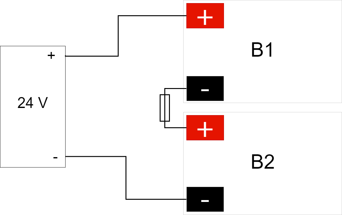
Connect the terminals correctly so that you do not damage the equipment.
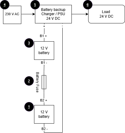
No. | Explanation |
|---|---|
1 | Battery 2. |
2 | Battery fuse. |
3 | Battery 1. |
4 | Incoming mains voltage, 230 V AC. |
5 | Rectifier 24 V DC. |
6 | Load, 24 V DC. |
Motherboard description
Connect in this order
To minimize the risk of short-circuit errors, connect the components to the motherboard in the following order.
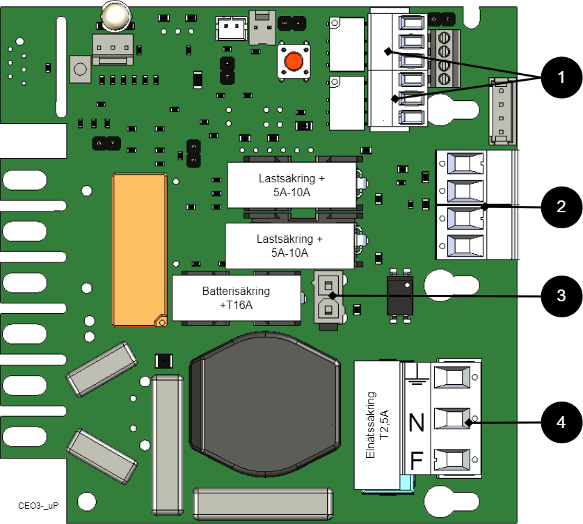
Nr | Explanation |
|---|---|
1 | Connect alarm. |
2 | Connect load. |
3 | Connect batteries |
4 | Connect mains. |
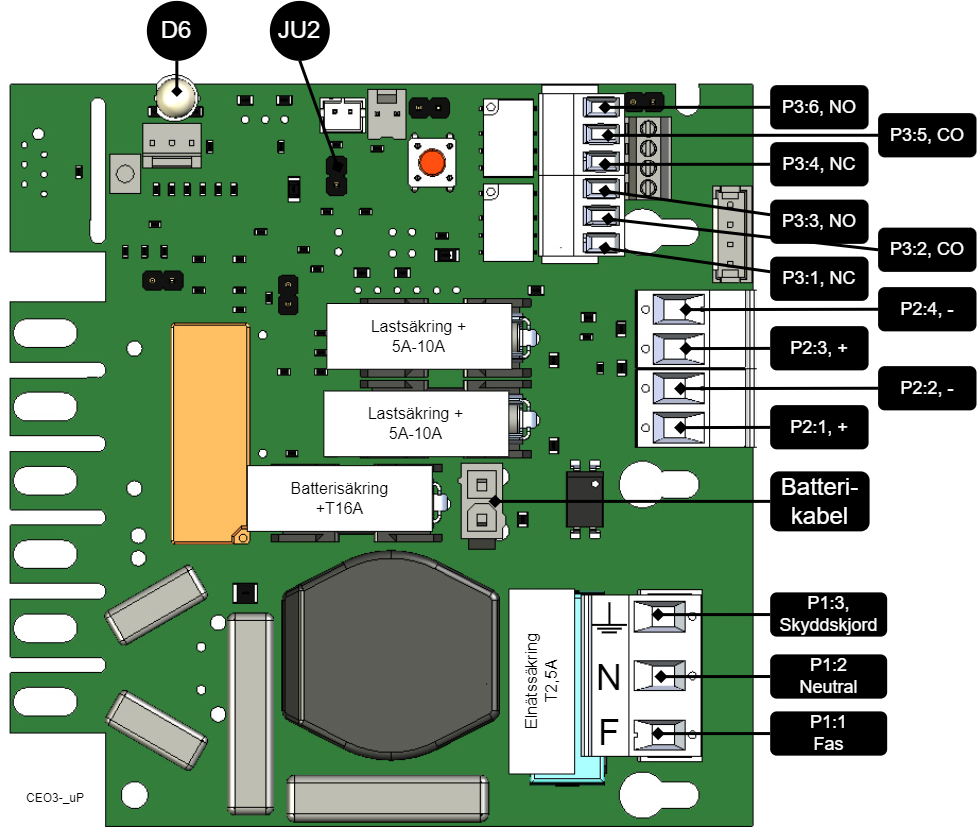
On PCB | Explanation |
|---|---|
D6 | Indicator diode. |
JU2 | Jumper for alarm control. When the jumper is mounted, the alarm limit is lowered. |
P1:1-3 | Mains connection, F, N, PE. |
P2:1-2 | Load output, + / -. |
P2:3-4 | Load output, + / -. |
P3:1-3 | Alarm output, NC, CO, NO. |
P3:4-6 | Alarm output, NC, CO, NO. |
Connect alarm on P3
Alarm is connected to terminal P3
P3:1-6 | Explanation |
|---|---|
Sum alarm | |
P3:1 | NC |
P3:2 | CO |
P3:3 | NO |
Sum-alarm* | |
P3:4 | NC |
P3:5 | CO |
P3:6 | NO |
Total alarm: Broken fuse on load, broken fuse from external distribution board, broken battery fuse, low battery voltage in battery operation, batteries not connected, overvoltage.
Connect load
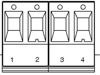
Circuit board number | Explanation |
|---|---|
P2: 1 | Connection for load 1 + |
P2: 2 | Connection for load 1 - |
P2: 3 | Connection for load 2 +. |
P2: 4 | Connection for load 2 -. |
Max current
The maximum current must not be exceeded. Max current is indicated on the rating plate on the device.
Danger
Mains voltage must be disconnected when working with stripped cables. It is the installer's responsibility to ensure that the correct skills are available for connecting 230 V to the unit. Maximum cable area is 4 mm2
Connect mains
Before connecting, the supply circuit should be disconnected and voltage-free. Verify that the conductor area and cable type meet the applicable installation rules and that the strain relief and insulation levels comply with the requirements for 230 V AC
After connection, all screw connections should be checked and tightened. Tensioning shall only take place after mechanical protection, caps and housing have been reassembled and comply with the contact protection according to EN 62368-1
Secure F and N with cable ties.
Important
Protective earth (PE) must be connected to the PE terminal on the motherboard. The motherboard is grounded via its mounting points in the enclosure, ensuring proper potential equalization between PCB and enclosure. Also the cover is grounded through ground cable/earth braid between cover and enclosure to maintain continuity and EMC
Mains wiring must be kept separate from other wiring to avoid EMC interference.
The protective earth (PE) must be connected to the PE terminal on the motherboard. The motherboard is grounded via its mounting points in the enclosure, ensuring correct equipotential bonding between the circuit board and the enclosure. The cover is also grounded via a grounding cable / grounding braid between the cover and the enclosure to maintain continuity and EMC function.
Check that the marking on the circuit board matches the wiring order on the terminal block.
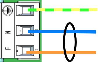
Connect the mains cable to the terminal block before it is re-inserted into the motherboard. Secure L (F in picture) and N with cable ties for electrical safety.
Letter | Explanation |
|---|---|
L | Fas |
N | Neutral |
PE |
Control alarm limit
Alarm for low battery voltage in battery operation can be controlled.
Fuses
Unit | Fuse | Type | Explanation |
|---|---|---|---|
All units | F1 | T2,5A | Mains fuse |
| F2, F6 | T10A | Load fuse + |
All units | F7 | T16A | Battery fuse |
Warning for replacing fuses (current strength, A)
There is a risk of damage if the fuse is changed to a larger one than what the unit is delivered with. The function of the fuse is to protect the connected load and cables against damage and fire. It is not possible to change the fuse to a larger one to increase the power output.
The differences between PoE switches
Product | PoE switch installed | Can additional PoE switches be installed? |
|---|---|---|
PoE M-switch 4p FLX M | A four 4 port PoE Switch | No . |
Commissioning - how to start the unit
Connect in this order
To minimize the risk of short-circuit errors, connect the components to the motherboard in the following order.
Nr | Explanation |
|---|---|
1 | Connect alarm. |
2 | Connect load. |
3 | Connect batteries |
4 | Connect mains. |
Connect batteries.
Connect fuses.
Plug in PoE and other loads.
Screw the mains cable into the terminal and attach the terminal to the motherboard.
Switch on mains voltage.
The unit works normally when the indicator LED on the outside of the cabinet door lights up with a solid green light. See front panel for other status indications.
It may take up to 72 hours for the batteries to be fully charged.
How the PoE switch software is accessed
How the software is accessed in the PoE Switch
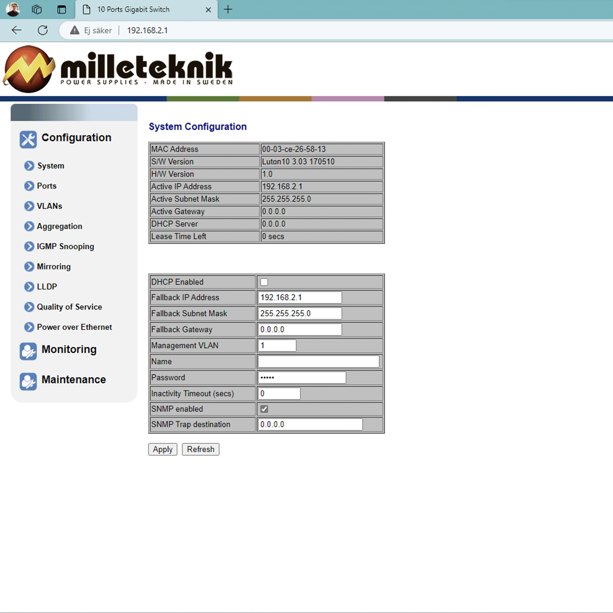
This section shows how to log in to the switch's configuration web page.
To configure the software in the switch, the correct IP address needs to be set on the computer.
Access to the switch's software is through a browser, (such as: Chrome, Edge, Firefox, etc.).
Follow the steps to access the switch's settings.
Note
The settings shown are settings for PC, (Windows 7 - Windows 11). Windows and names may vary between different versions of Windows. Unfortunately, we cannot provide support for settings of your computer.
Note
IP address of the switch (factory setting): 192.168.2.1
Password (factory setting): admin
Notice
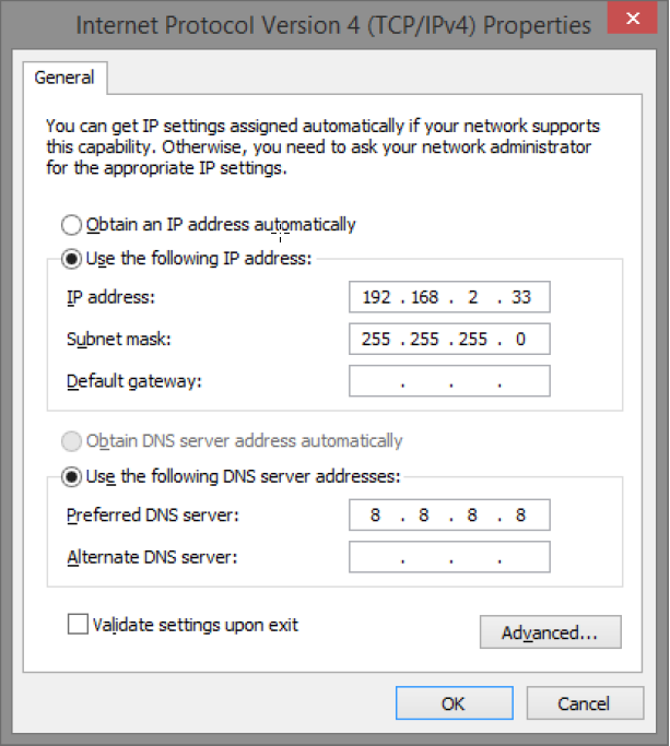
The address of the PoE switch is: 192.168.2.1 and username and password are: admin/admin The IP address in the switch is static (fixed) and therefore the computer's IP address and subnet mask must be static.
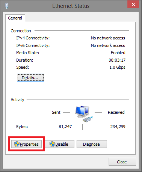
Open settings and go to Network and Internet -> Advanced network settings. Open more network card options.
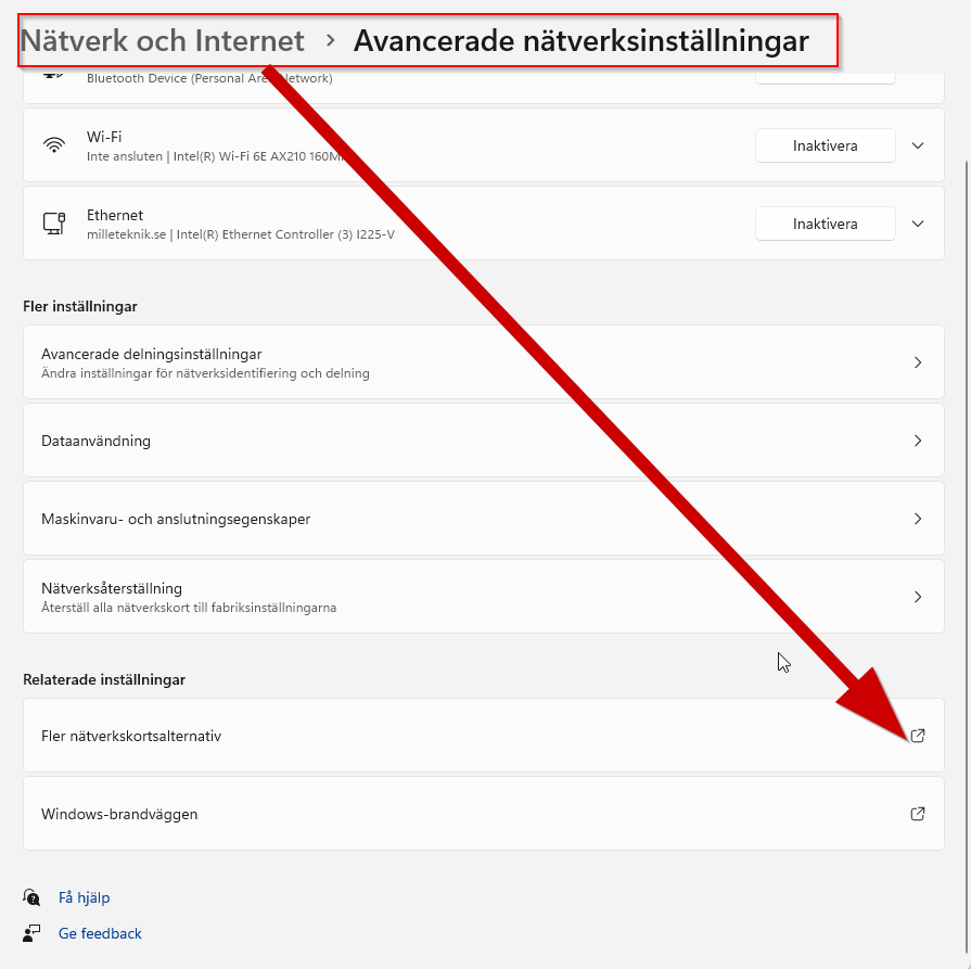
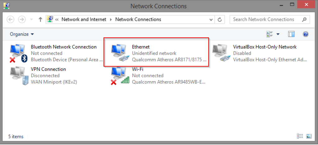
A Network Connections window will appear showing all available network connections on the computer. Double-click the network connection you use to connect to the switch.
Ethernet status window appears. Click the button Characteristics as shown in the figure below.
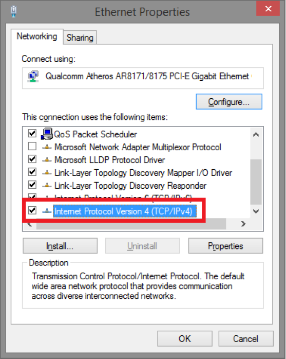
Double-click: Internet Protocol Version 4 (TCP / IPv4).
Set the computer's IP address and subnet mask as shown in the figure below. By default, the product's IP address be 192.168.2.1. You can set any IP address as long as it is not the same as your switch's IP address and is in the same network segment as your switch's IP address. Press on OK to apply the TCP/IPv4 settings you just made. Now you can connect to your switch using a web browser (Chrome, Edge or Firefox).
Connect an RJ-45 cable and connect to the PoE switch.
Log in to the PoE switch
Note
IP address of the switch (factory setting): 192.168.2.1
Password (factory setting): admin
Note
If you get a warning that the page is not secure/the connection is not private, click "advanced" and then "continue".
Start the browser on your computer.
Login to PoE switch.
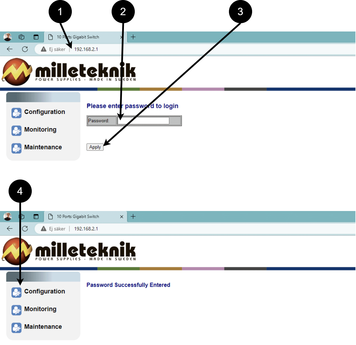 Table 10. Log in to the switch.
Number
Explanation
1
IP address of the PoE switch: 192.168.2.1
2
Password: admin
3
Apply = Ok
4
Menu in the PoE switch
Configuration
System, configuration
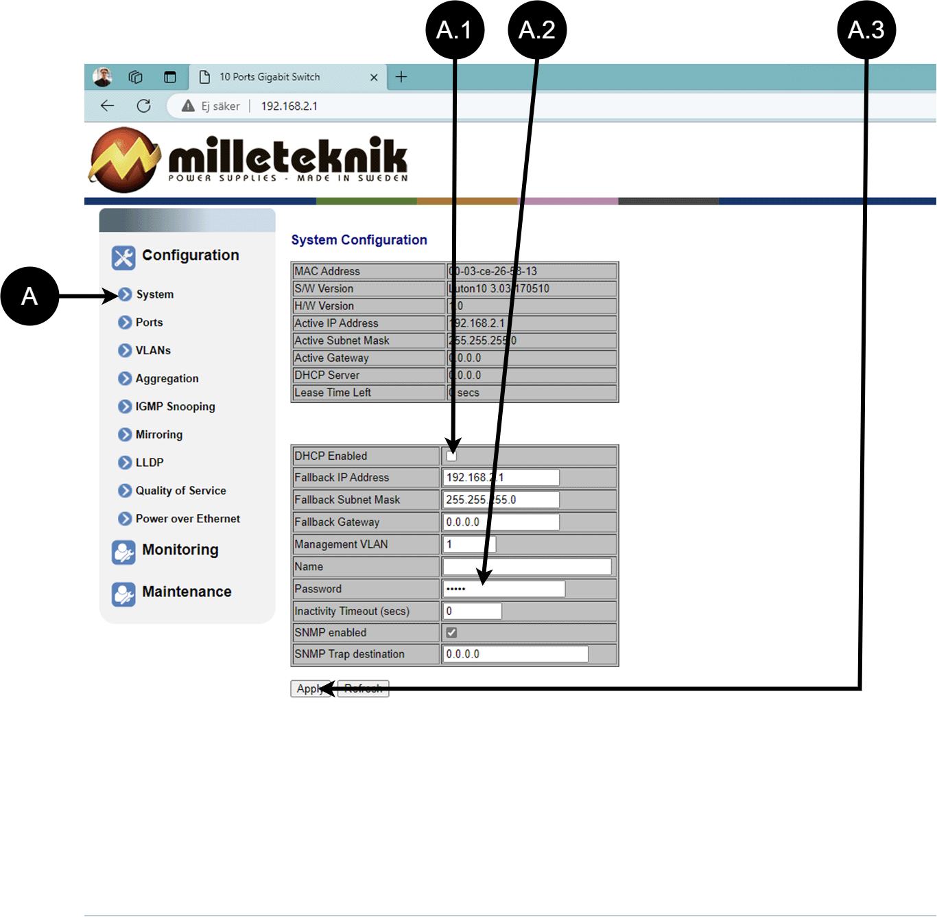
Letter, number | Explanation |
|---|---|
A | PoE switch system configuration page |
A.1 | Tick here if you are going to use DHCP, see warning below. |
A.2 | Changes the factory default password, (admin). |
A.3 | If you have made any changes, you need to click "Apply" to save the changes. |
Ports, configuration
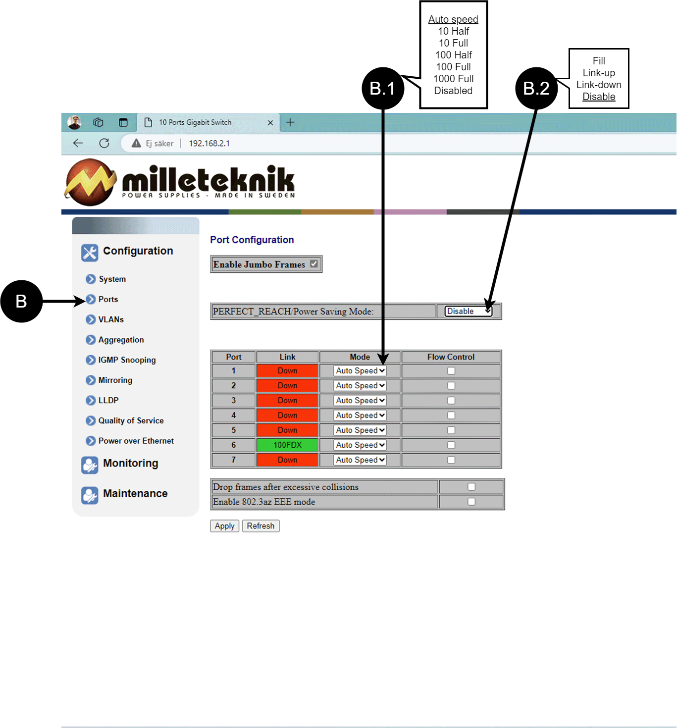
Letter, number | Explanation |
|---|---|
B | Gates |
B.1 | This setting normally does not need to be changed. Select the speed of the PoE switch's ports. |
B.2 | This setting normally does not need to be changed. |
VLAN configuration
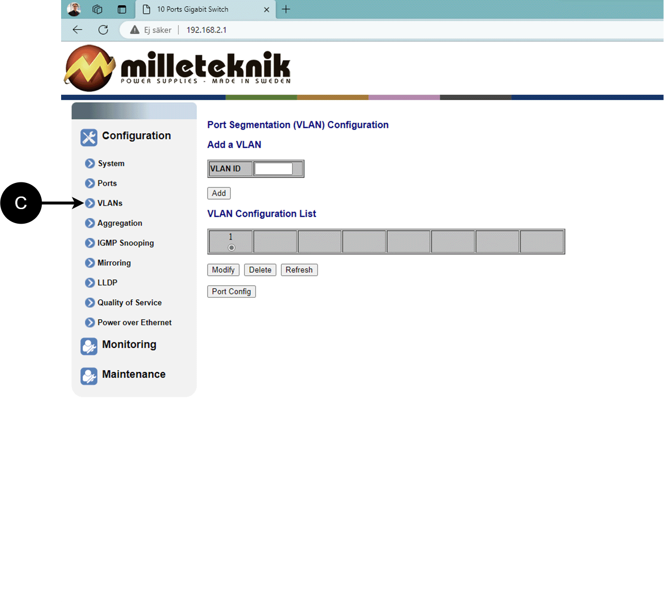
C: Configuration of Virtual LAN.
Aggregation, configuration
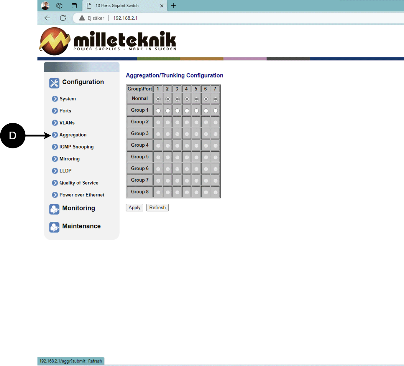
D: Load balancing between the ports.
IGMP Snooping, configuration
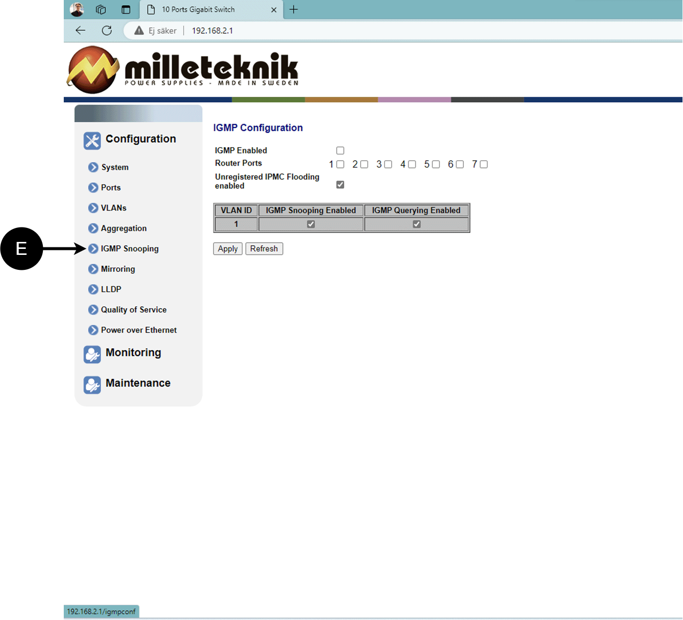
E: Switch that controls reception.
Mirroring, configuration
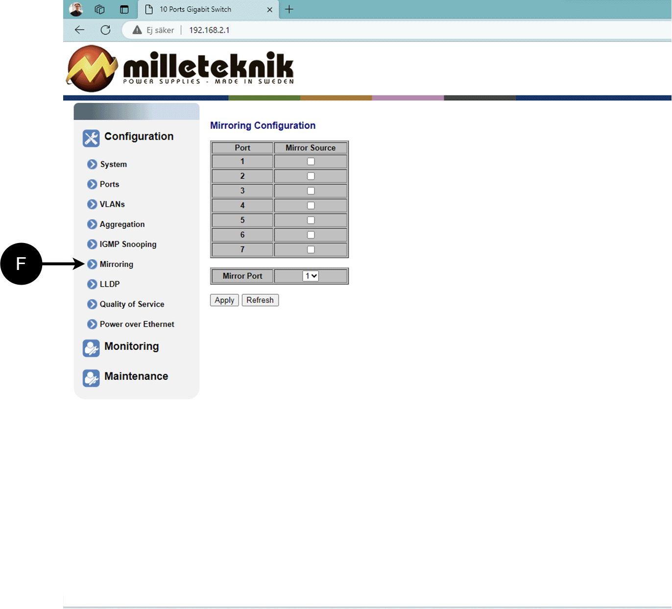
F: Mirroring of ports.
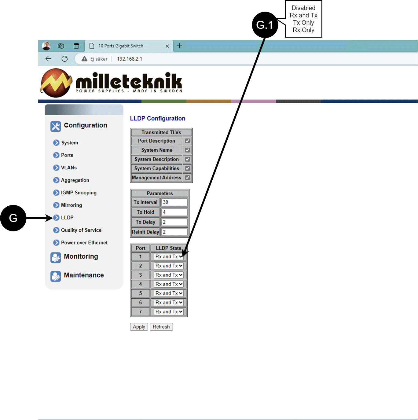
LLDP configuration
Letter, number | Explanation |
|---|---|
G | LLDP stands for "Link Layer Discovery Protocol", which is a network protocol standard used to discover and communicate information about network devices connected to the same Ethernet network. The protocol allows devices such as switches and routers to send and receive messages containing information about the device's identification, capabilities, and connection topology. |
G.1 | RX and TX are abbreviations used in electronics, communications, and computer networking to indicate the direction of data flow between devices. RX: The abbreviation "RX" stands for "Receive" or "Reception". It indicates that the device is receiving data or signals from another device. When a device has an RX input, it means that it is designed to receive data or information from a transmitting device. TX: The abbreviation "TX" stands for "Transmit" or "Transmission". It indicates that the device is transmitting data or signals to another device. If a device has a TX output, it means that it is designed to transmit data or information to a receiving device. These abbreviations are especially common when it comes to data communication, such as in the context of network cables where there are specific RX and TX wires that allow for two-way communication between devices. |
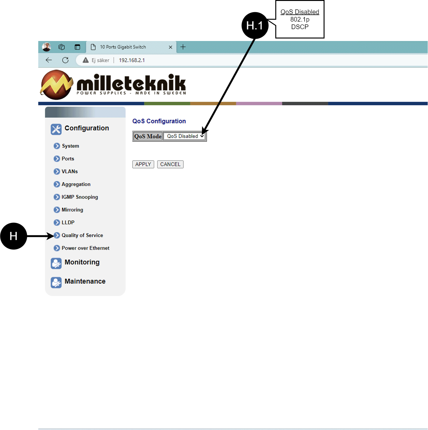
QoS, configuration
Letter, number | Explanation |
|---|---|
H | QoS gives different network traffic different priority, helping to ensure that important services are delivered with sufficient bandwidth and minimal delay even when the network is under load. |
H.1 | Sets whether QoS is active. |
PoE, configuration
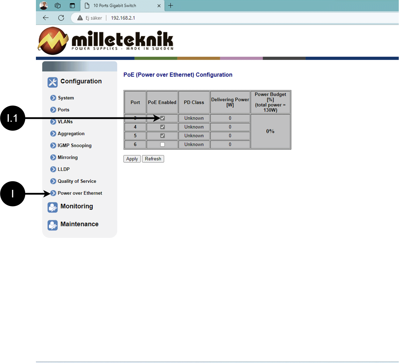
Letter, number | Explanation |
|---|---|
I | Power over Ethernet |
I.1 | Turns PoE function/port on or off. Remember to press "Apply" to save changes. |
Monitoring
Statistics, overview
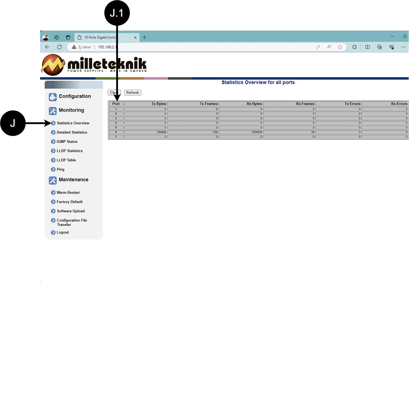
Letter, number | Explanation |
|---|---|
J | Statistics, overview |
J.1 | Traffic per port. |
Statistics, detailed
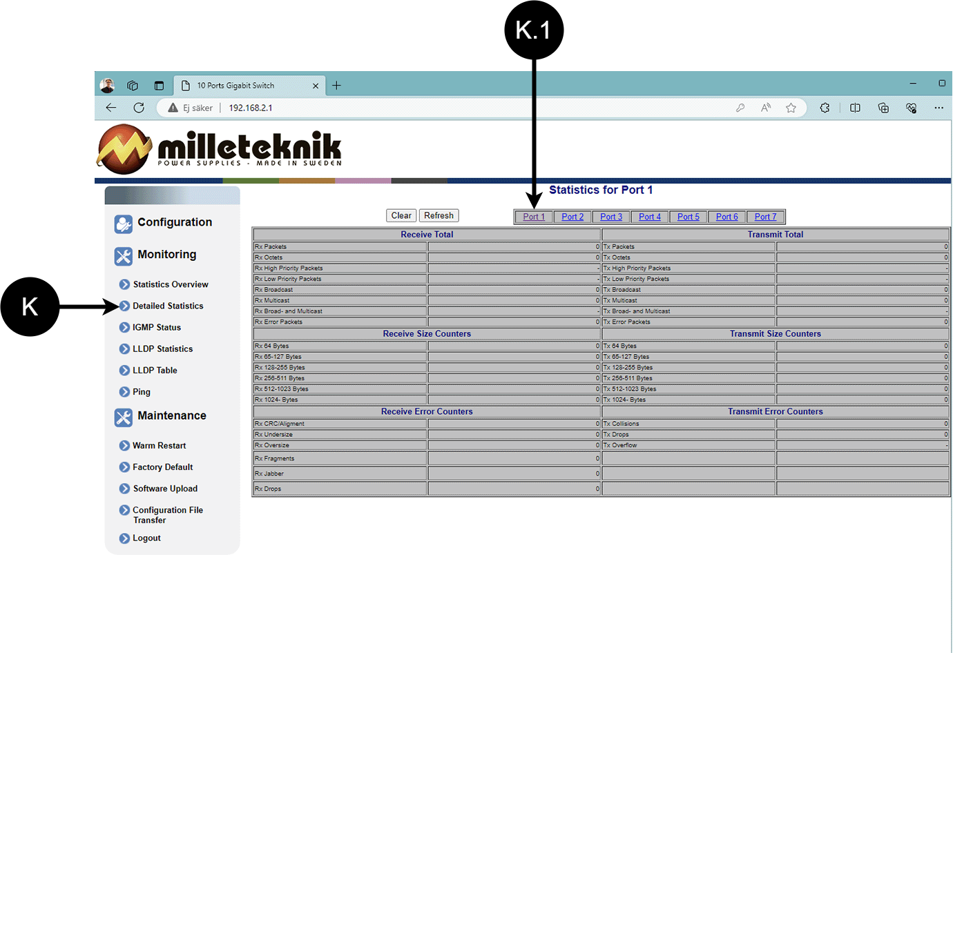
Letter, number | Explanation |
|---|---|
K | Detailed statistics |
K.1 | Select the port for which you want statistics. |
IGMP status
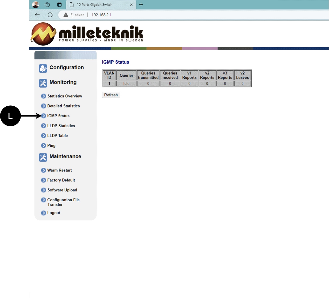
L: Status of IGMP
LLDP statistics
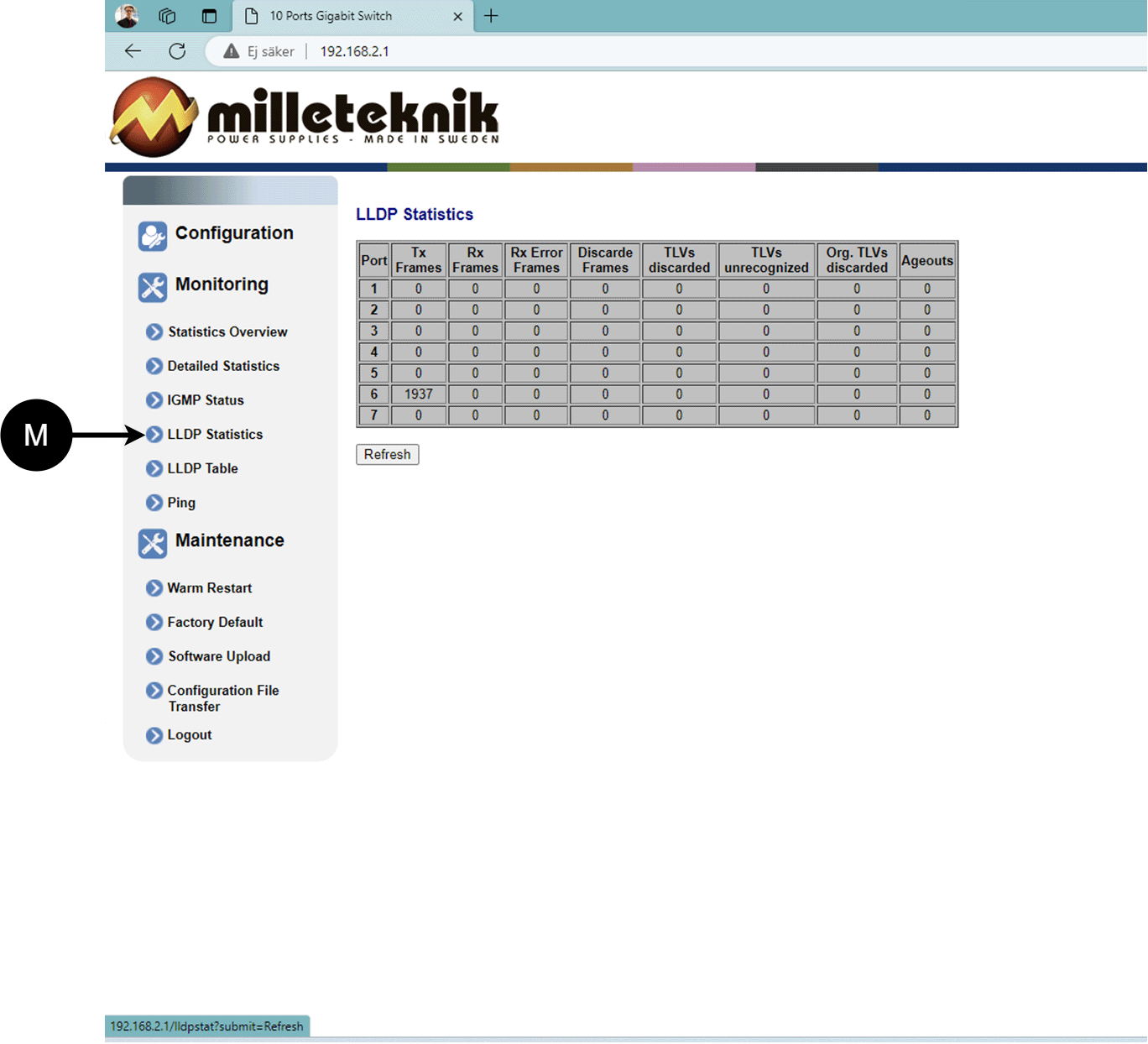
M: LLDP statistics
LLDP table
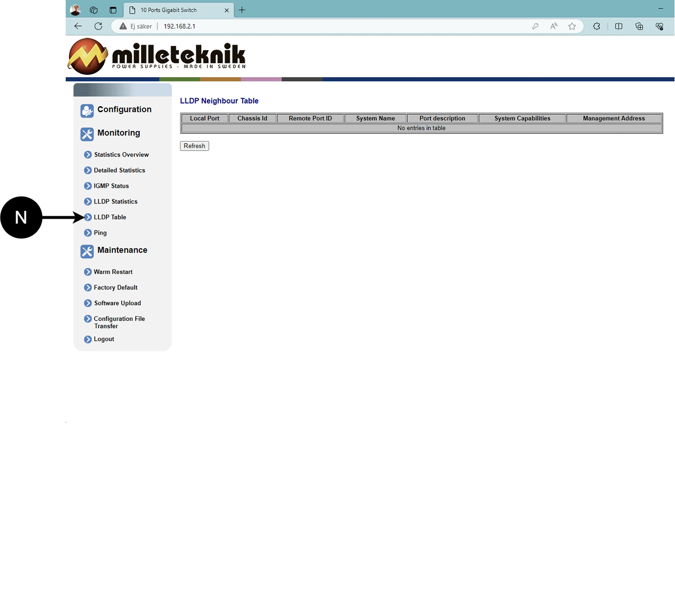
N: LLDP overview.
Ping
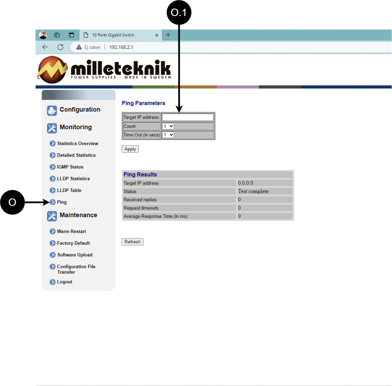
Letter, number | Explanation |
|---|---|
O | Ping |
[sv] O.1 | Input address to test the connection and response time. |
Maintenance
Reboot
Warning
Restart is done by PoE switch, battery backup is not restarted. Upon reboot, connected devices will lose connection. Alarm can be set to battery backup, but it disappears when the PoE switch is back on.
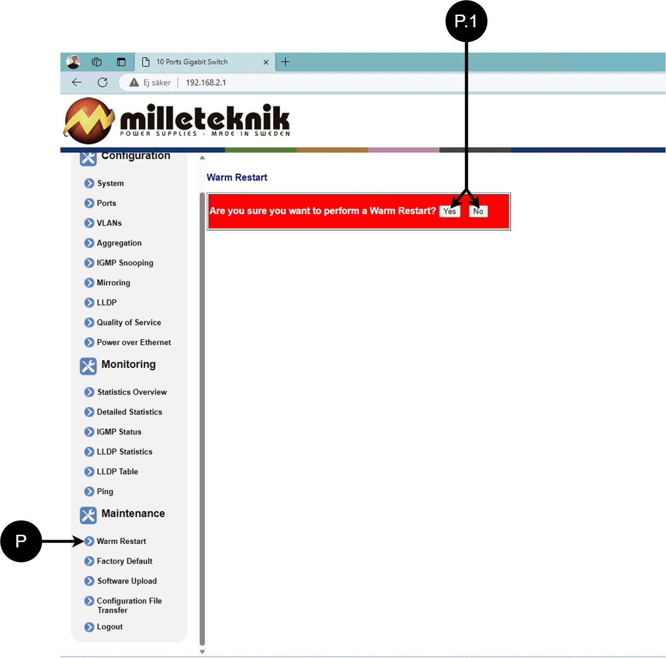
Letter, number | Explanation |
|---|---|
P | Rebooting the PoE switch. |
P.1 | Select "Yes" to reboot the switch. |
Factory reset
Warning
Factory reset is done by PoE switch. Battery backup is not restored. On reset, connected devices will lose connection. Alarm can be set to battery backup, but it disappears when the PoE switch is back on.
Factory reset of the switch can only be done from the software's (this) interface.
Recommendation: Keep IP address 192.168.2.1 and note password.
Important
During a factory reset, all settings, including IP settings, are lost. Save configuration before factory reset. See Upload new software
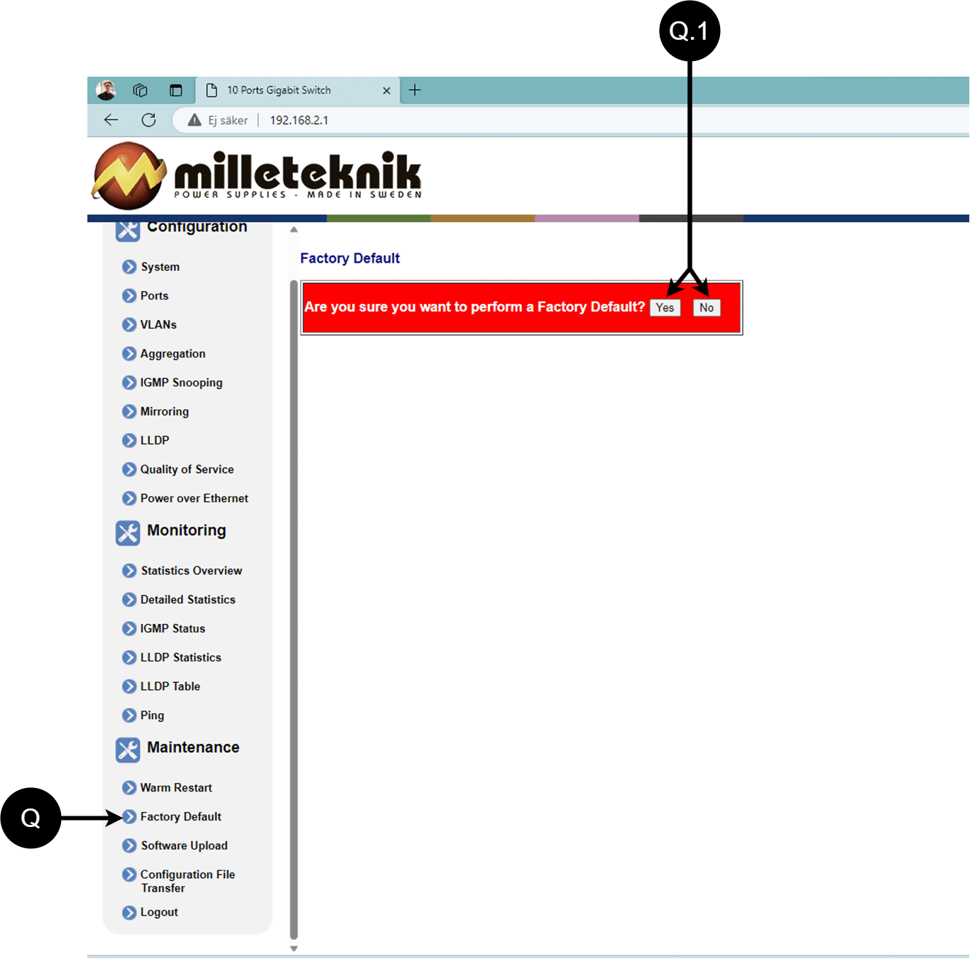
Letter, number | Explanation |
|---|---|
Q | Factory reset the PoE switch. |
Q.1 | Select "Yes" to factory reset the PoE switch. |
Upload new software
Warning
Only use software you received from Milleteknik's support. Milleteknik assumes no responsibility for software or consequences such as damage to the device or peripheral equipment or other damage that may arise from uploading unapproved software.
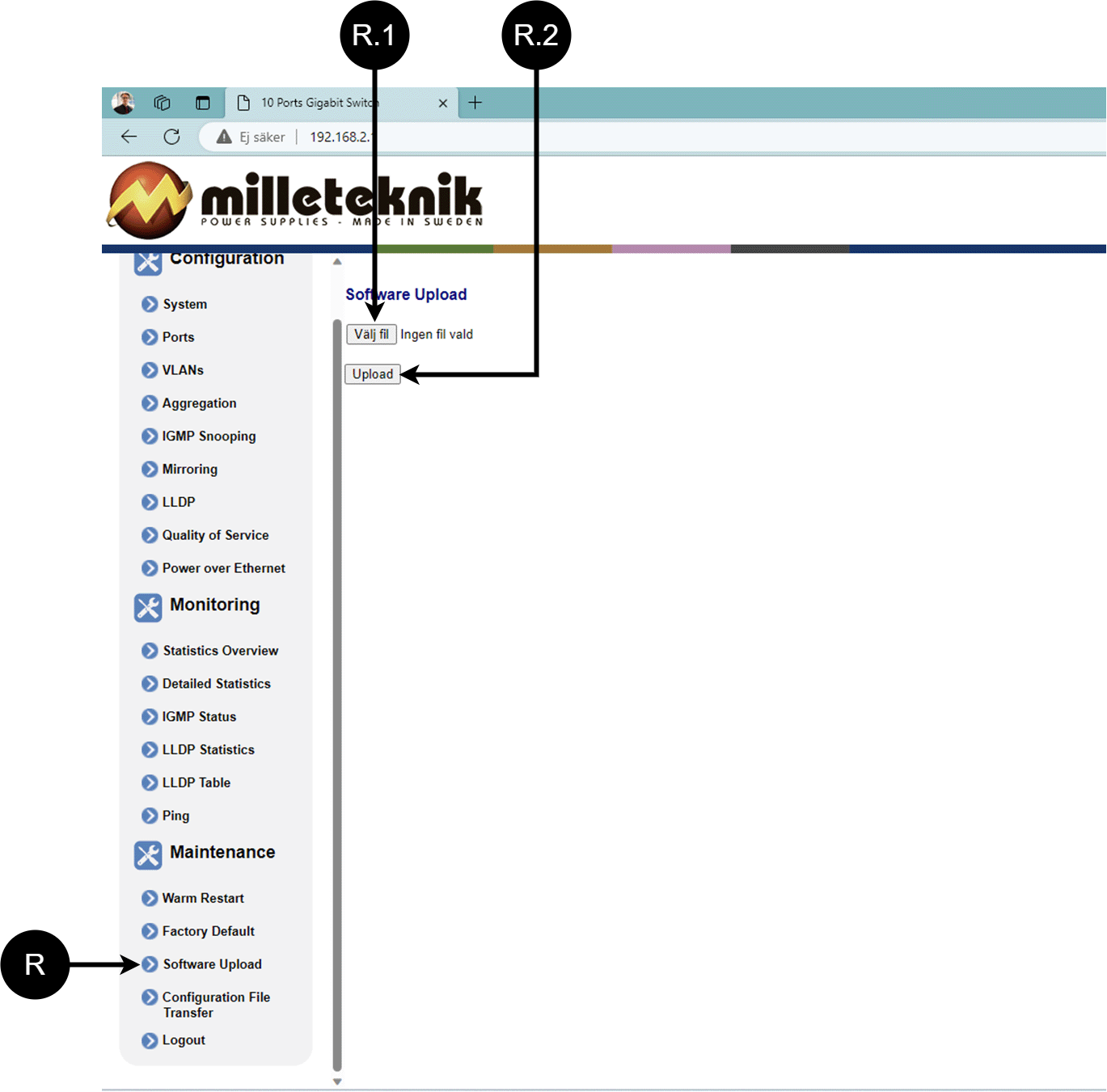
Letter, number | Explanation |
|---|---|
R | Upload new software to the Switch. |
R.1 | Navigate to the location on your computer where you saved the file. |
R.2 | Click "Upload" to upload the software. |
Load and save configuration file
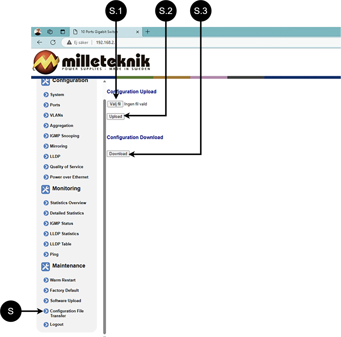
Letter, number | Explanation | ||||||||||||||||||||||||||||||||||||||||||||||||
|---|---|---|---|---|---|---|---|---|---|---|---|---|---|---|---|---|---|---|---|---|---|---|---|---|---|---|---|---|---|---|---|---|---|---|---|---|---|---|---|---|---|---|---|---|---|---|---|---|---|
S | Upload or download the switch's configuration. | ||||||||||||||||||||||||||||||||||||||||||||||||
S.1 | Select new configuration file. | ||||||||||||||||||||||||||||||||||||||||||||||||
S.2 | Upload new configuration file. | ||||||||||||||||||||||||||||||||||||||||||||||||
S.3 | Download configuration file to computer[a]. | ||||||||||||||||||||||||||||||||||||||||||||||||
[a] Newer Windows computers do not allow *.cfg files to be downloaded without additional approval in the browser when downloading. Antivirus programs may delete the file during download. | |||||||||||||||||||||||||||||||||||||||||||||||||
Sign out
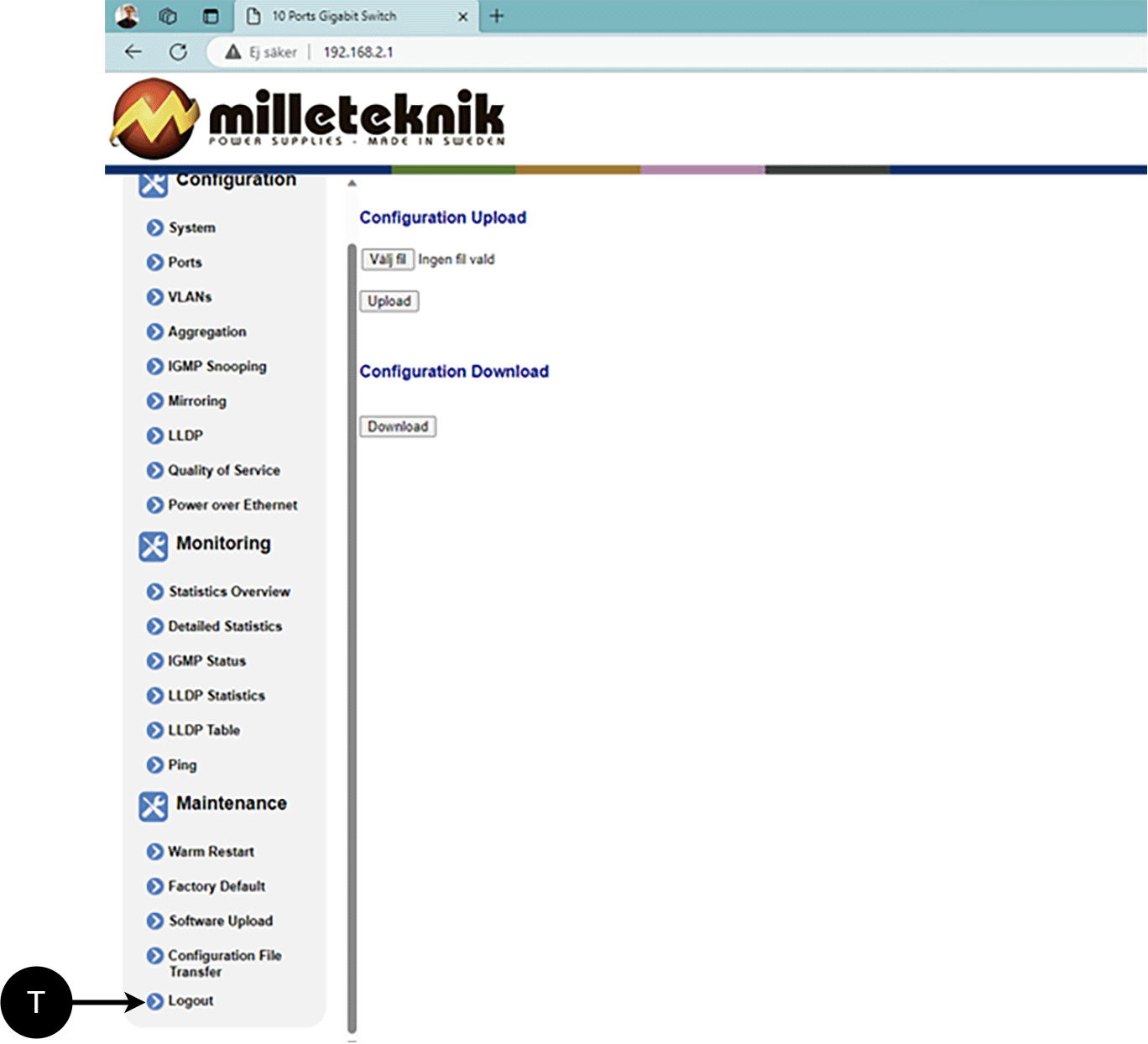
T: Log out of the switch. This does not affect the operation of the switch.
About this information
All information is published subject to possible errors. Information is updated without prior notice. |
Publication date 2026-07-08
Alarm displayed on cabinet door
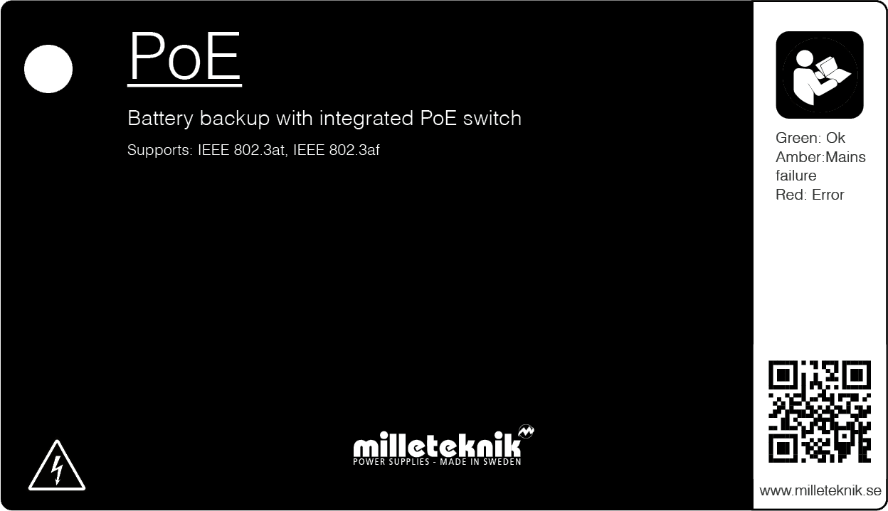
In normal mode, the indicator LED shows a solid green light.
 |
The indicator diode shows | Explanation |
|---|---|
Solid green light | Normal operation. |
Solid amber glow | Mains failure. |
Solid red light | Battery not connected / blown fuse. |
When operating system: If the indicator LED is off, deep discharge protection has been activated.
Notice
If the indicator light flashes every 15 seconds, the battery is fully charged and the charge is in rest phase to extend battery life. In the event of a power failure during the rest phase, the battery backup switches to battery operation as usual
Maintenance
The system with the exception of batteries is maintenance-free when installed in an indoor environment.
battery change
If possible, disconnect mains (voltage) when replacing the battery.
Disconnect battery cables. Note how battery cables are mounted before removing them.
Remove battery fuse between batteries.
Insert and fasten the new batteries.
Connect the battery cables in the same way as before.
Connect battery fuse between batteries.
Switch on mains voltage. The indicator LED may not be green (up to 72 hours), until the batteries are charged.
Test the system by briefly disconnecting the mains voltage, (= the load is driven by the batteries), and then switch on the mains voltage again.
Product sheet - power supply / battery backup
Product Sheet
PoE
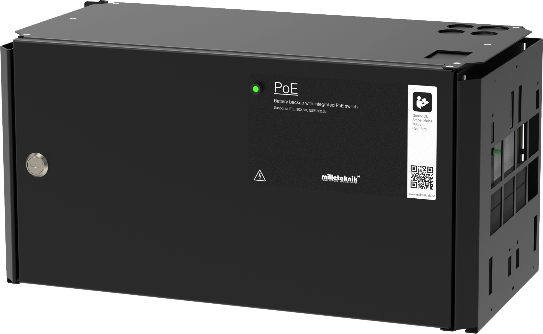
Managed PoE switch with 4 PoE Ports.
Product Identification
Product designation | Article number | E-number (SE) |
|---|---|---|
PoE M-Switch 4p FLM | FM01N10224P01004PM | 51 728 96 |
Technical description
Power supply with backup power to power PoE devices such as surveillance cameras and other PoE powered devices. A plate for keystone modules makes the installation of PoE devices easier An additional load output to power other 24 V applications.
Batteries, for example, drive the access system further when the power grid goes down.
Plate for fastening of keystone modules.
Constant output voltage, 24 V (which is boosted to 48 V), regardless of battery or mains operation, which allows the full battery capacity to be used.
For mounting on a wall or in a 19" rack.
Quick Facts | |||||||||||||||||||||||||||||||||||||||||||||||||
|---|---|---|---|---|---|---|---|---|---|---|---|---|---|---|---|---|---|---|---|---|---|---|---|---|---|---|---|---|---|---|---|---|---|---|---|---|---|---|---|---|---|---|---|---|---|---|---|---|---|
Supply voltage (V) | 230V AC, +/- 10%, 47Hz- 63Hz | ||||||||||||||||||||||||||||||||||||||||||||||||
Voltage out (V) | 54.6 V DC, (48 V DC) 27.3 V DC, (24 V DC) Also applicable in battery operation. | ||||||||||||||||||||||||||||||||||||||||||||||||
Current output (A), max load current output. | 5 A on 24 V load output | ||||||||||||||||||||||||||||||||||||||||||||||||
Batteries[a] | 2 x 20 Ah | ||||||||||||||||||||||||||||||||||||||||||||||||
[a] Recommended. If batteries are included, it is indicated, otherwise batteries are ordered separately | |||||||||||||||||||||||||||||||||||||||||||||||||
Areas of application
Areas of application | Yes | No |
|---|---|---|
IP camera, power supply. | ✔ | |
Networked devices that can be powered by PoE. | ✔ |
Electrical data
Electrical data | |||||||||||||||||||||||||||||||||||||||||||||||||
|---|---|---|---|---|---|---|---|---|---|---|---|---|---|---|---|---|---|---|---|---|---|---|---|---|---|---|---|---|---|---|---|---|---|---|---|---|---|---|---|---|---|---|---|---|---|---|---|---|---|
Supply voltage | 230V AC, +/- 10%, 47Hz- 63Hz | ||||||||||||||||||||||||||||||||||||||||||||||||
Charge current | Depending on the power outlet. Max 10A | ||||||||||||||||||||||||||||||||||||||||||||||||
Efficiency[a] | 90% | ||||||||||||||||||||||||||||||||||||||||||||||||
Standby consumption | 1.27 W | ||||||||||||||||||||||||||||||||||||||||||||||||
Voltage out | 54.6 V DC, (48 V DC) 27.3 V DC, (24 V DC) Also applicable in battery operation. | ||||||||||||||||||||||||||||||||||||||||||||||||
Current (A)[b] | 5 A on 24 V load output | ||||||||||||||||||||||||||||||||||||||||||||||||
Power (W) | 30.8W per port | ||||||||||||||||||||||||||||||||||||||||||||||||
[a] At rated load. [b] Power outlet/load is specified as max, normal current output should be 80% of max. | |||||||||||||||||||||||||||||||||||||||||||||||||
Fuses | |
|---|---|
Mains fuse | 2.5 A |
Load fuses | Fuse on supply to PoE switch : T10A Load output fuse: 10 A |
Battery fuse | 30A |
Circuit Boards | Internal power consumption (during battery operation) | Other. info |
|---|---|---|
4p Managed PoE Switch | Data is missing | |
CEO3 48V | 32 mA |
Load outputs
Load outputs | |
|---|---|
Number of loading outputs | PoE switch can drive load to four PoE devices and motherboards can drive one (1) 24 V load output to power other applications. |
POE outputs | |
|---|---|
Number of PoE ports (RJ-45) | 4 |
PoE budget | 336 W |
POE Budget/Max Power Per Port | ! 4 30.8 W. |
Number of LAN ports | 2 |
Network ports/interfaces, RJ-45 | 100 Mbit/s |
Managed | No |
Alarm and protection
Alarm and protection | Yes | No | |||||||||||||||||||||||||||||||||||||||||||||||
|---|---|---|---|---|---|---|---|---|---|---|---|---|---|---|---|---|---|---|---|---|---|---|---|---|---|---|---|---|---|---|---|---|---|---|---|---|---|---|---|---|---|---|---|---|---|---|---|---|---|
Battery charge protection/controlled charging[a] | ✔ Batteries are charged with a maximum of 0.5 A.[b] | ||||||||||||||||||||||||||||||||||||||||||||||||
✔ | |||||||||||||||||||||||||||||||||||||||||||||||||
Overload Protection/Surge Protection | ✔ | ||||||||||||||||||||||||||||||||||||||||||||||||
Over-temperature protection | ✔ | ||||||||||||||||||||||||||||||||||||||||||||||||
Short circuit protection | ✔ | ||||||||||||||||||||||||||||||||||||||||||||||||
[a] Controlled charging protects and extends battery life. [b] Factory setting. Adjustable in PowerWatch [c] When the deep discharge protection is activated, the device turns off and the LED goes out. | |||||||||||||||||||||||||||||||||||||||||||||||||
Communication and Indications
Communication and Indications | Yes | No | Other. info. |
|---|---|---|---|
Communication | ✘ | ||
RJ-45 | ✔ | Refer to manual for alarms that PoE switch can provide. | |
Port control via connected computer | ✔ | ||
Indicators/LEDs | ✔ | LED displays information and alarms on circuit boards and on the outside of the housing. |
Battery
Enclosure and Mechanics
Enclosure and Mechanics | |
|---|---|
Type | Universal enclosure for wall and rack |
IP class | IP32 |
Material | Powder coated sheet metal. |
Colour | Black |
Height units | 5 |
Cable grommets | 4 pcs |
Knockout hole | 1 pc. on the back |
Lock | ✔ 2 keys included |
Fan in enclosure | ✔✘ |
Assembly, installation and eligibility requirements
Fitting | Yes | No |
|---|---|---|
19" rack. | ✔ | |
Wall. | ✔ |
Installation | Yes | No |
|---|---|---|
Fixed installation. | ✔ |
Dimensions, weight and packaging information
Net weight | Weight with packaging |
|---|---|
7.8 kg | 8.55kg |
Packaging | |
|---|---|
Packaging | Cardboard and impact protection in cardboard. |
Quantity in pack | 1 pc. |
Packaging Type (GS1 T0137) | BX box. |
Conditions EUR pallet | EUR pallets may not be stacked during transport or storage. Stacking may result in damage to product and packaging |
Transport environment | The product must be protected from condensation and direct precipitation during transportation. |
Transport temperature (without battery) | −30 °C to +70 °C |
Storage environment | Dry indoor environment, protected from condensation. Relative humidity: max 95%, non-condensing |
Storage temperature without batteries | −20 °C to +60 °C |
Contact
Department | |
|---|---|
Switchboard | 031-340 02 30 |
Support and technical issues | support@milleteknik.se |
Sales | sales@milleteknik.se |
WWW | www.milleteknik.se |
Address | Ögärdesvägen 8B, 433 30 Partille |
About this information
All information is published subject to possible errors. Information is updated without prior notice. |
Publication date 2026-07-08
Compliance and regulatory compliance
Delivery time, warranty and terms
Delivery time, warranty and terms | |||||||||||||||||||||||||||||||||||||||||||||||||
|---|---|---|---|---|---|---|---|---|---|---|---|---|---|---|---|---|---|---|---|---|---|---|---|---|---|---|---|---|---|---|---|---|---|---|---|---|---|---|---|---|---|---|---|---|---|---|---|---|---|
Warranty period[a] | The product has a two (2) year warranty against manufacturing defects.In addition to the regular warranty period, an additional three (3) year warranty can be purchased. | ||||||||||||||||||||||||||||||||||||||||||||||||
Special warranty conditions | Batteries and wear parts are not covered by warranty. See also general terms and conditions. | ||||||||||||||||||||||||||||||||||||||||||||||||
General Terms and Conditions | ALEM09 with exceptions, see: www.milleteknik.se/conditions/ | ||||||||||||||||||||||||||||||||||||||||||||||||
Support | Telephone support and email support during the warranty period are free of charge. For spare parts that are not covered by warranty, there is a charge | ||||||||||||||||||||||||||||||||||||||||||||||||
Delivery and stock | |||||||||||||||||||||||||||||||||||||||||||||||||
Delivery time[b] | Or as per agreement. Delivery from factory, transportation time is added. | ||||||||||||||||||||||||||||||||||||||||||||||||
[a] If the device is purchased through a wholesaler or other supplier, other warranty conditions may apply. [b] In the case of larger orders, delivery time increases, acc. to agreement. | |||||||||||||||||||||||||||||||||||||||||||||||||
Operation and maintenance
Operation | Data | Other. info | |||||||||||||||||||||||||||||||||||||||||||||||
|---|---|---|---|---|---|---|---|---|---|---|---|---|---|---|---|---|---|---|---|---|---|---|---|---|---|---|---|---|---|---|---|---|---|---|---|---|---|---|---|---|---|---|---|---|---|---|---|---|---|
Environment | Indoor environmental class 1. | ||||||||||||||||||||||||||||||||||||||||||||||||
Operating temperature (recommended) | +15°C to +25°C | For the best battery life. Higher temperatures significantly shorten the life of the batteries. | |||||||||||||||||||||||||||||||||||||||||||||||
Operating temperature (permissible)[a] | +5°C to +40°C | Class 1 according to EN 50131-6/ EN 60839-11 | |||||||||||||||||||||||||||||||||||||||||||||||
Load, power supply | 80% | Average load shall not exceed 80% of the rated capacity of the power supply. | |||||||||||||||||||||||||||||||||||||||||||||||
Ventilation, free distance around the enclosure. | 100 mm | Ventilation openings must not be blocked or covered. | |||||||||||||||||||||||||||||||||||||||||||||||
[a] Specifies the permissible ambient temperature range in which the product can operate without damage. See also table on battery life. | |||||||||||||||||||||||||||||||||||||||||||||||||
Yes | No | Interval | Other. info |
|---|---|---|---|
✔ | Annually | The fan should be cleaned annually. Battery terminal voltage must be measured. Ensure that the average load does not exceed 80% of the rated capacity of the power supply. |
Certifications and approvals
Complies with | Directives |
|---|---|
PoE | IEEE 802.3af, IEEE 802.3at/30.8 W up to type2, class 4. |
C.E. | CE marking according to Regulation (EC) No 765/2008 |
RoHS | RoHS Directive 2011/65/EU, including amendment (EU) 2015/863 |
EMC | EMC Directive 2014/30/EU |
Electric (LVD) | Low Voltage Directive 2014/35/EU |
Environmental data
Environmental data | J/N | Informație | Other. info. | ||||||||||||||||||||||||||||||||||||||||||||||
|---|---|---|---|---|---|---|---|---|---|---|---|---|---|---|---|---|---|---|---|---|---|---|---|---|---|---|---|---|---|---|---|---|---|---|---|---|---|---|---|---|---|---|---|---|---|---|---|---|---|
Building Product Declaration (BPD) | ✔ | Yes, see iBvd at www.milleteknik.se. | - | ||||||||||||||||||||||||||||||||||||||||||||||
REACH Information Obligation (EC) No 1907/2006 | ✔ | Yes, see the DoC at www.milleteknik.se The product complies with REACH Regulation (EC) No 1907/2006. | If empty, the product is not covered. | ||||||||||||||||||||||||||||||||||||||||||||||
SVHC substances, CAS/EC | ✔ | Yes, lead, 7439-92-1/231-100-4 | For text, see iBvd at www.milleteknik.se. If blank, substance is missing. | ||||||||||||||||||||||||||||||||||||||||||||||
Subject to the RoHS Directive, (EU) 2015/863) | ✔ | Yes, see the DoC at www.milleteknik.se | |||||||||||||||||||||||||||||||||||||||||||||||
WEEE 2012/19/EU | ✔ | The product contains electrical components or wiring and is covered by the WEEE Directive (2012/19/EU). | If empty, the product is not covered. End-of-life products must be returned to a recycling centre | ||||||||||||||||||||||||||||||||||||||||||||||
Battery Regulation (EU) 2023/1542 | ✗ | ||||||||||||||||||||||||||||||||||||||||||||||||
SCIP No 2008/98/EC | ✔ | Yes, registered under the EU Waste Directive where applicable, (2008/98/EC). | If empty, no SCIP number is needed. | ||||||||||||||||||||||||||||||||||||||||||||||
Conflict minerals (EU) 2017/821 | ✗/✗/✗/✗/✔ | No=Gold, Tungsten, Tantalum, Cobalt. Yes=Tin | Tin in solders in printed circuit boards purchased through a Swedish supplier. | ||||||||||||||||||||||||||||||||||||||||||||||
Contains nanomaterials: EC 1272/2008 | ✗ | The product does not contain nanomaterials. | |||||||||||||||||||||||||||||||||||||||||||||||
Ecodesign 2009/125/EC | Milleteknik's products are intended for professional use and are therefore not directly covered by the Ecodesign Regulation (EU 2019/1782). As some components may be covered, we nevertheless disclose relevant information[a], where applicable, to provide our customers with confidence in their choice. | ||||||||||||||||||||||||||||||||||||||||||||||||
Machine Directive 2006/42/EC | The product is part of electrical systems, is subject to the relevant electrical and safety directives and is not a machine according to the Machinery Directive (2006/42/EC). Will be replaced by Machinery Regulation (EU) 2023/1230, which will apply in 2027. | ||||||||||||||||||||||||||||||||||||||||||||||||
The product is designed and constructed for a long service life, which reduces the environmental impact. The life of the product (except wearing parts) depends on, among other things, environmental factors, mainly ambient temperature, unforeseen load on components such as lightning strikes, external impact, handling errors, etc. Products are recycled, simply because they are modular, by being left at the nearest recycling station or sent back to the manufacturer.[b]Contact your distributor for more information. | |||||||||||||||||||||||||||||||||||||||||||||||||
[a] Standby consumption and power. [b] Costs incurred in connection with recycling are not reimbursed. | |||||||||||||||||||||||||||||||||||||||||||||||||


Manufacturer and country of origin
Manufacturer[a] | Milleteknik AB | ||||||||||||||||||||||||||||||||||||||||||||||||
Customs State. Nos. | 85044095[b] | ||||||||||||||||||||||||||||||||||||||||||||||||
Country of origin | Sweden | ||||||||||||||||||||||||||||||||||||||||||||||||
[a] Manufacturer is the trademark indicated on the product, regardless of what is stated in this product sheet. [b] Verify with the Customs Ombud/Customs Service for export/import; alternative classification 85044055 may become applicable if the product is assessed as a battery charger. | |||||||||||||||||||||||||||||||||||||||||||||||||
Appendix
Backup operating time on batteries
The reserve operating time in battery operation depends on how large a load is connected to the power supply. If the load varies, as with frequent opening of door locks, the time that batteries can continue to power the security system decreases. To get an estimate of reserve operating times see: www.milleteknik.se/Manualer/FaQ/Reservdrifttider/
Eligibility requirements, installation
Eligibility requirements vary between countries. The table summarizes national requirements for fixed installation and connection of equipment with a plug socket, respectively.
Options on the secondary side of the product, such as 12 V, 24 V or 48 V DC, are connected according to the respective instructions. Work on the network connection of the product shall be carried out in accordance with national eligibility requirements
Permission Requirements for Installation | Fixed installation (230 V) | Plug | Other. info |
|---|---|---|---|
Sweden | ✔ | ✗ | Fixed installation may be performed by technicians but shall be under the responsibility of a qualified installer. (Electrical Safety Act, SS 436 40 00) Plug may be connected without authorization. |
Norway | ✔ | ✔ | Requirements for qualified electricians also for equipment with a plug socket in fixed installations. (NEK 400, DSB |
Finland | ✔ | ✗ | Plug may be connected without authorization. (Tukes, SFS 6000 |
Denmark | ✔ | ✗ | Plug may be connected without authorization. (Safety Board |
Germany | ✔ | ✗ | All fixed installations require a qualified electrician according to VDE 0100. Plug sockets may be connected without authorization, but only by person with basic electrical knowledge (“Elektrotechnisch unterwiesene Person”) |
Miscellaneous
The difference between PoE, PoE+ and PoE++.
Reference table: environmental classes according to EN 50130-5 (referred to in EN 50131-6)
Class | Type | Temperature range |
|---|---|---|
Environmental Class 1 | Heated indoors (type office/residence). | +5°C to +40°C |
Environmental Class 2 | Generally indoors (type warehouses/stairwells, not temperature controlled). | -10°C to +40°C |
Environmental class 3 | Protected outdoors. | -25°C to +50°C |
Environmental class 4 | Generally outdoors. | -25°C to +60°C |
Reference table: manufacturer's stated service life and recommended battery replacement
Battery Type (Design Life)[a] | Battery replacement time in normal operation, +20°C. | Replacement during hot operation, +30°C | Replacement during hot operation, +40°C | ||||||||||||||||||||||||||||||||||||||||||||||
|---|---|---|---|---|---|---|---|---|---|---|---|---|---|---|---|---|---|---|---|---|---|---|---|---|---|---|---|---|---|---|---|---|---|---|---|---|---|---|---|---|---|---|---|---|---|---|---|---|---|
3 - 5 years | 2 - 3 years | 1 - 1.5 years | 0.5 - 0.75 years | ||||||||||||||||||||||||||||||||||||||||||||||
6 - 9 years | 5 - 6 years | 2.5 - 3 years | 1.2 - 1.5 years | ||||||||||||||||||||||||||||||||||||||||||||||
10 - 12 years | 6 - 7 years | 3 - 3.5 years | 1.5 - 1.75 years | ||||||||||||||||||||||||||||||||||||||||||||||
15 + years | 10 - 12 years | 5 - 6 years | 2.5 - 3 years | ||||||||||||||||||||||||||||||||||||||||||||||
[a] Valid in case of completely unused battery stored under optimal conditions. | |||||||||||||||||||||||||||||||||||||||||||||||||
About this information
All information is published subject to possible errors. Information is updated without prior notice. |
Publication date 2026-07-08