
About this document
This document is subject to change without prior notice.
All information is published with reservation for printing errors.
Installation and commissioning
Instructions for installation and commissioning.
If
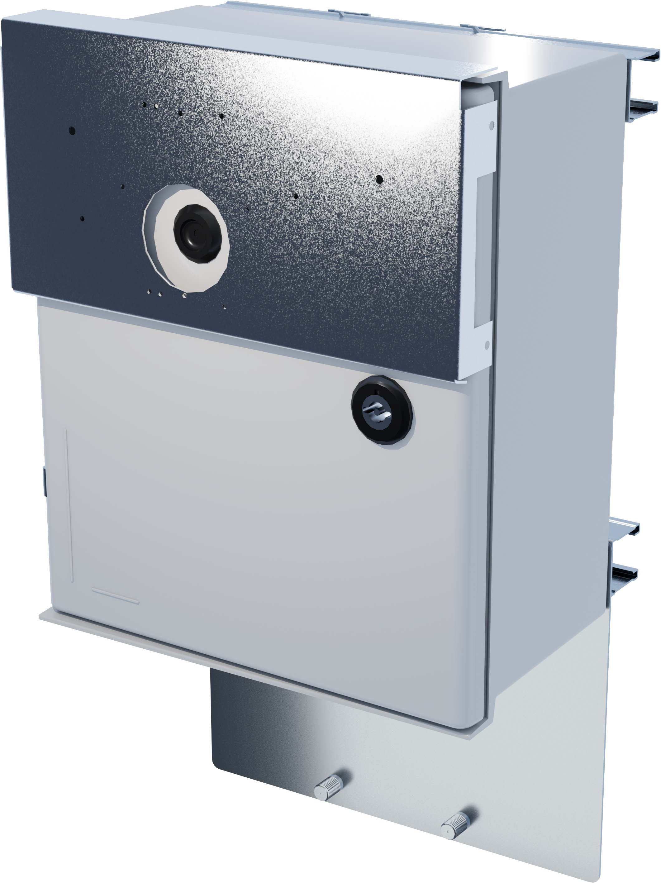
PoE Managed 4p 24V 5A OUT S is a power supply with PoE switch for outdoor use. Built to withstand Nordic conditions - summer as winter. The product is different from indoor battery backups from Milleteknik and some features have been added and
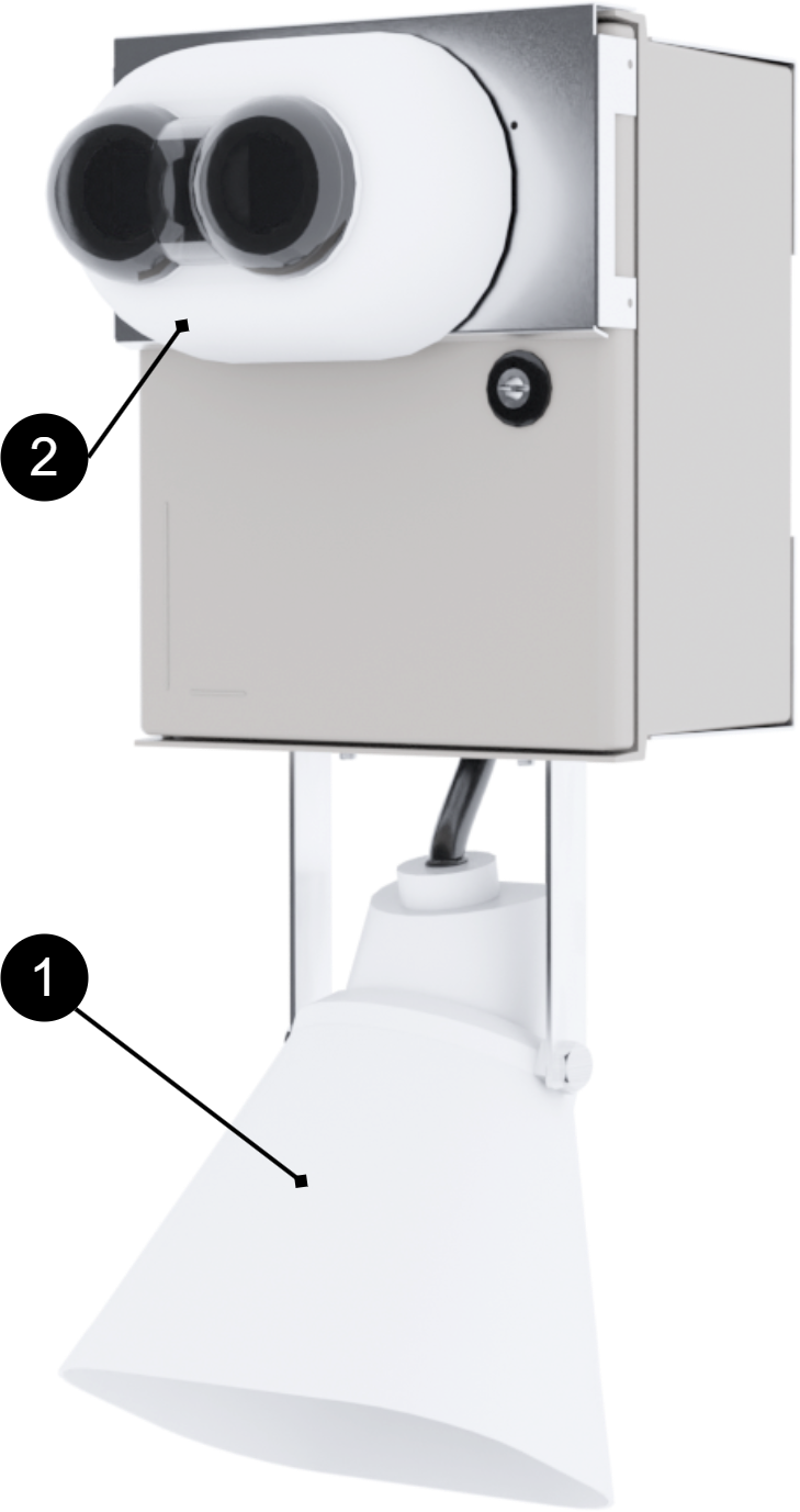
Examples of connected devices, here a camera and a speaker. Note that speakers can be mounted differently and are dependent on configuration
Enclosures
General assembly instructions
Mounting options and accessories
To ensure a smooth installation, we offer several custom mounts for our UT series enclosures (S, M and L). In the matrix below you will see which options are compatible
Please note that a wall mount is always included as standard with all models. For pole mounting or needing extra sun protection, separate optional kits are required
Accessories | Enclosure |
|---|---|
Pole Mount Kit for UT S and UT M | UT S and UT M |
Sun Shield Kit | UT S, UT M and UT L |
Mounting on pole
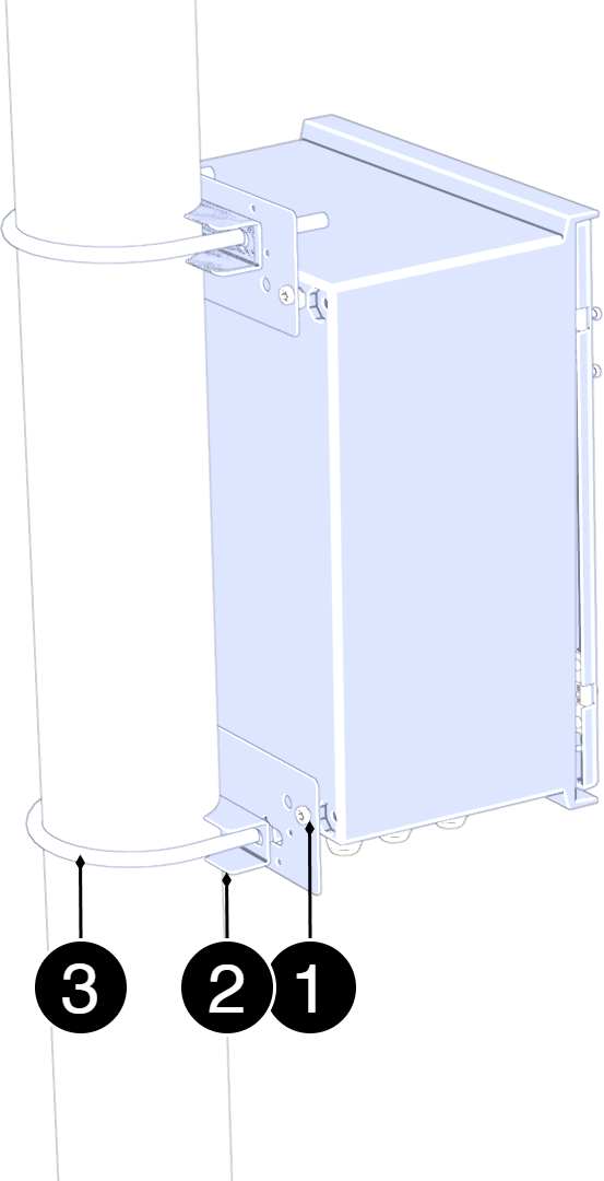
Mounting on pole
See component overview for screw, nut, washers and spacers.
No. | Explanation |
|---|---|
1 | Fastening plate. |
2 | Counter. |
3 | U-bolt. |
Assemble in this order:
Place the mounting plates (3) on the upper and lower attachment points of the enclosure and attach them lightly with the screws provided. Do not tighten finally yet.
Pass the lower U-bolt (2) around the post and through the holes in the lower mounting plate. Install washers and nuts. Tighten lightly.
Pass the upper U-bolt (2) around the post and through the holes in the upper mounting plate. Install washers and nuts
Adjust the position of the enclosure so that it is in solder and centered toward the post.
Tighten all nuts in sequence: — lower U-bolt — upper U-bolt — screws to the mounting plates
Check the attachment by lightly loading the enclosure forward/backward to ensure stable mounting.
Component overviews
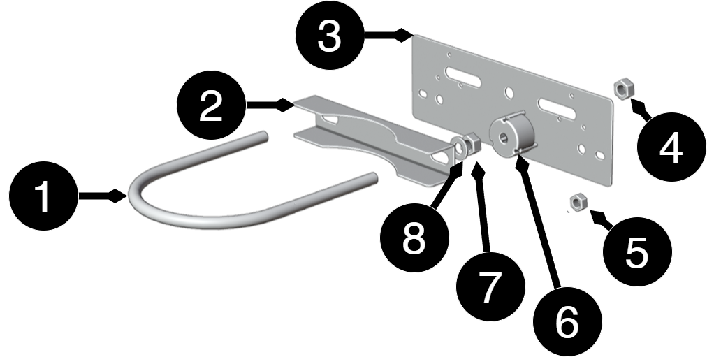
Component overview Mounting Kits
No. | Explanation | Size | Number |
|---|---|---|---|
1 | Fixing plate | 125mm | 2 |
2 | U-bolt for pole | - | 2 |
3 | Washers and nuts | - | 2 |
4,7 | Nut | M10 | 4 |
5 | Nut | M6LM | 8 |
6 | Distance | Ø 36 mm, depth 20 mm | 4 |
8 | Washer | 10 (5x20x2) | 4 |
Component overview
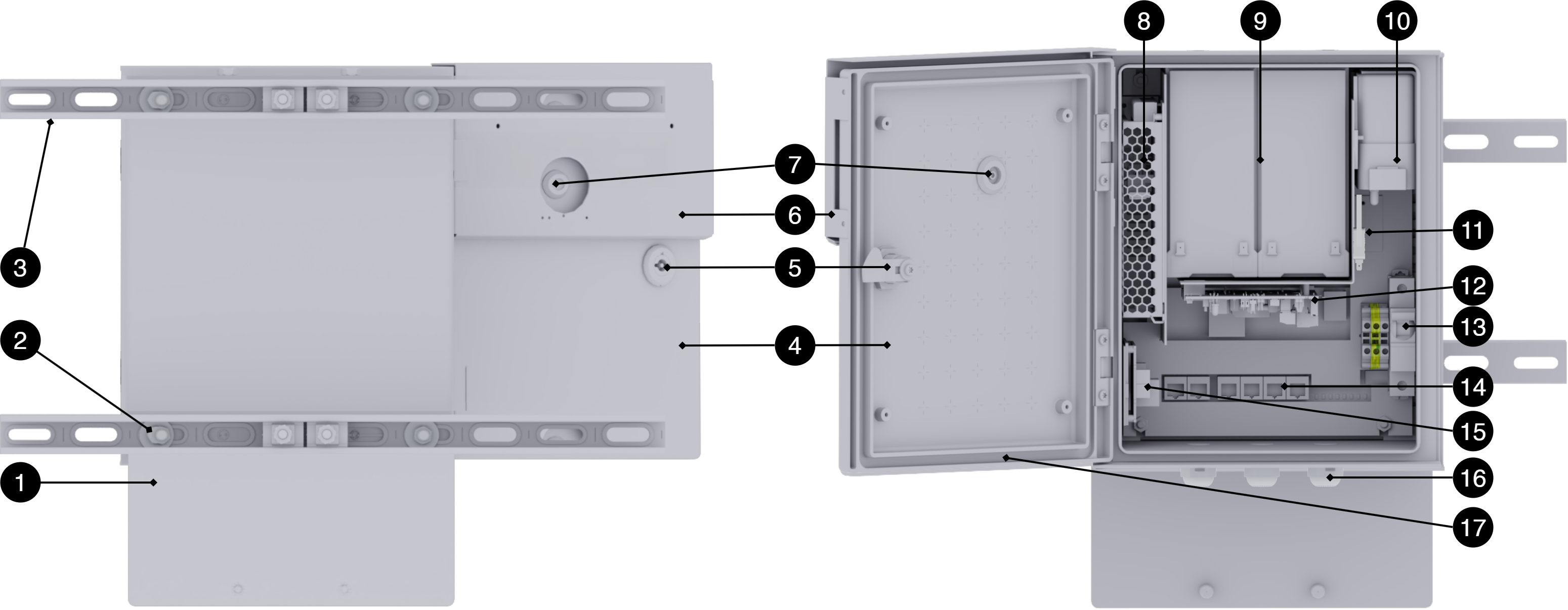
No | Explanation |
|---|---|
1 | Bracket for mounting camera, siren, speaker, etc. |
2 | Fastening screw and nut. |
3 | Scan. |
4 | Door. |
5 | Lock. |
6 | Mounting plate on door for mounting camera, siren, speaker, etc. |
7 | Cable entry in door. |
8 | Power supplies |
9 | Batteries. |
10 | Mobile modem location. |
11 | Control boards, electronics, |
12 | Sabotage contact. |
13 | Fuse for power supply. |
14 | Poe card. |
15 | Booster card for power supply to PoE card. |
16 | Cable grommets. |
17 | In the door there is a heating loop and thermostat control, (not shown in the picture). |
Switching on power supply
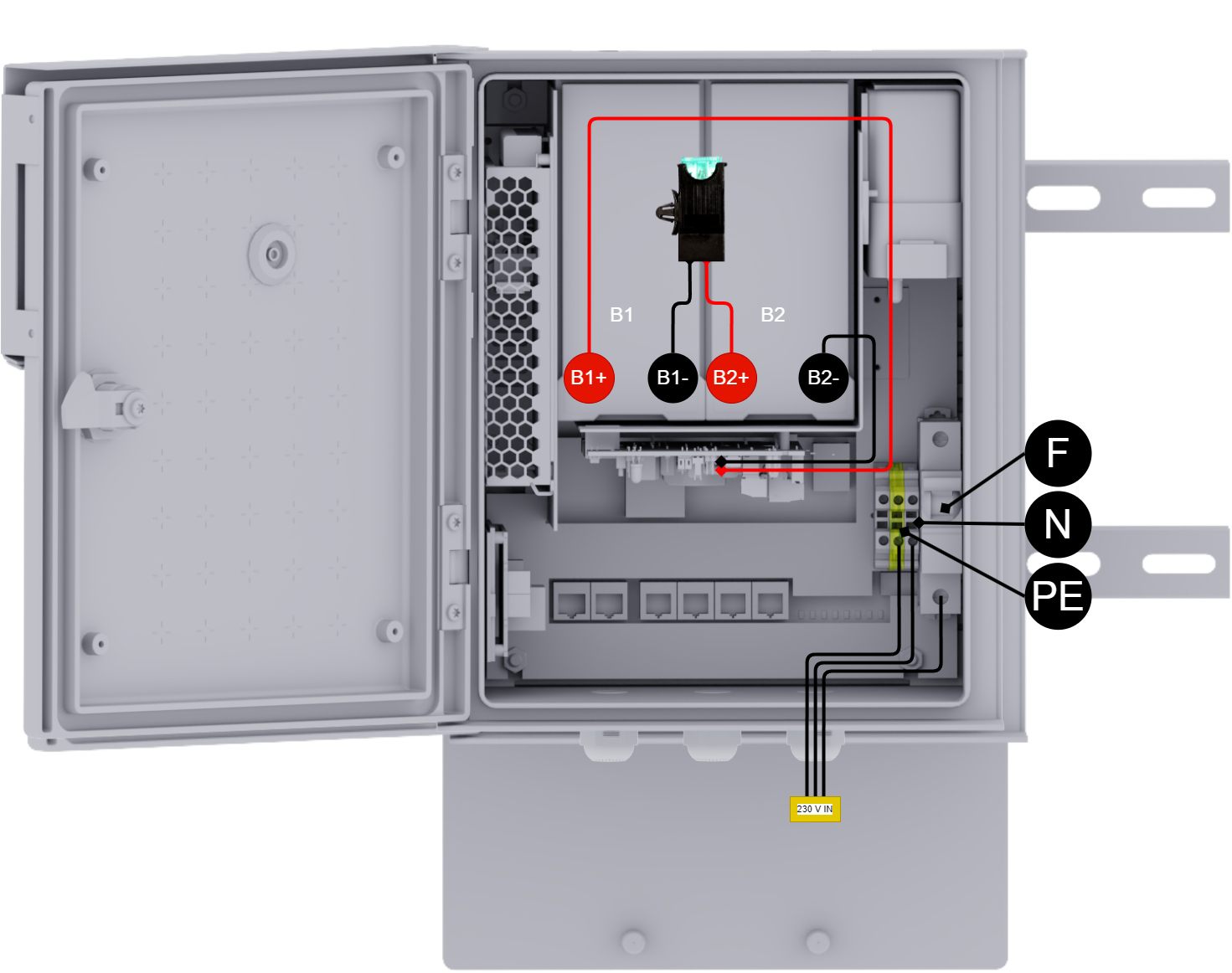
Batteries | Explanation |
|---|---|
B1+ | Connects to control boards. |
B1- | Connects to fuse. |
B2+ | Connects to fuse. |
B2- | Connects to control boards. |
Designation | Explanation |
|---|---|
F | Fas |
N | Neutral/Zero |
P.E. | Shelter soil |
230 V IN | Incoming power supply, 230 VAC. |
How the PoE switch software is accessed
How the software is accessed in the PoE Switch
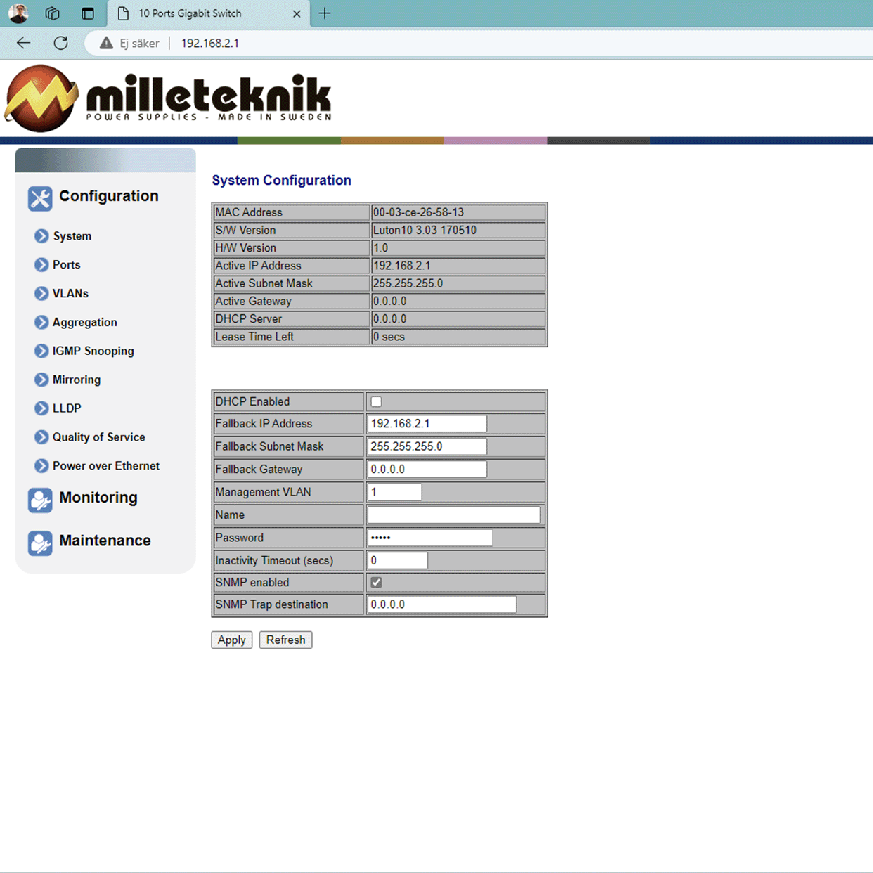
This section shows how to log in to the switch's configuration web page.
To configure the software in the switch, the correct IP address needs to be set on the computer.
Access to the switch's software is through a browser, (such as: Chrome, Edge, Firefox, etc.).
Follow the steps to access the switch's settings.
Note
The settings shown are settings for PC, (Windows 7 - Windows 11). Windows and names may vary between different versions of Windows. Unfortunately, we cannot provide support for settings of your computer.
Note
IP address of the switch (factory setting): 192.168.2.1
Password (factory setting): admin
Notice
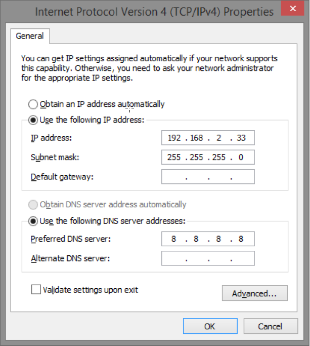
The address of the PoE switch is: 192.168.2.1 and username and password are: admin/admin The IP address in the switch is static (fixed) and therefore the computer's IP address and subnet mask must be static.
Open settings and go to Network and Internet -> Advanced network settings. Open more network card options.
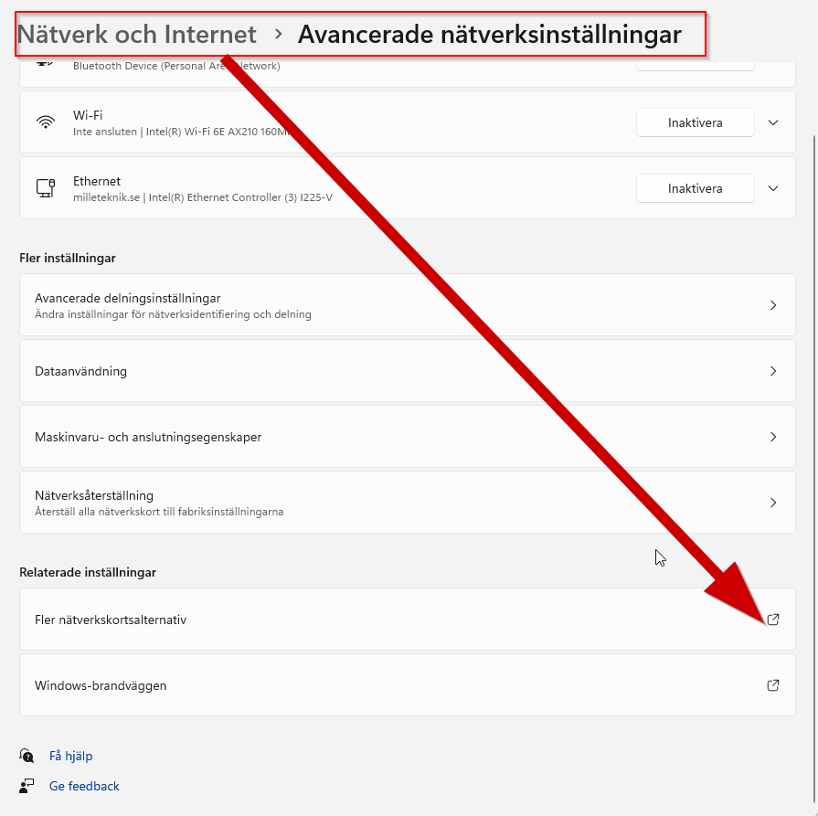
A Network Connections window will appear showing all available network connections on the computer. Double-click the network connection you use to connect to the switch.
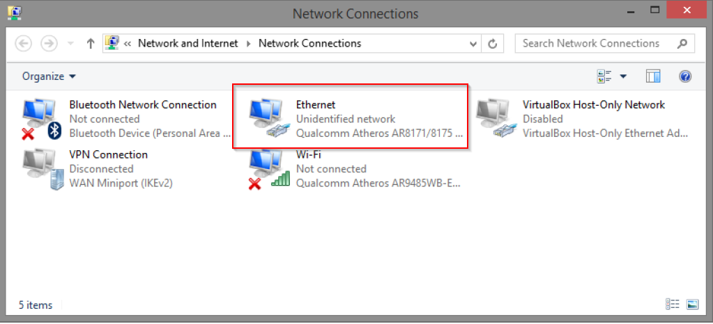
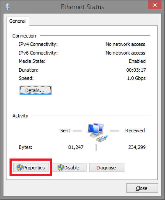
Ethernet status window appears. Click the button Characteristics as shown in the figure below.
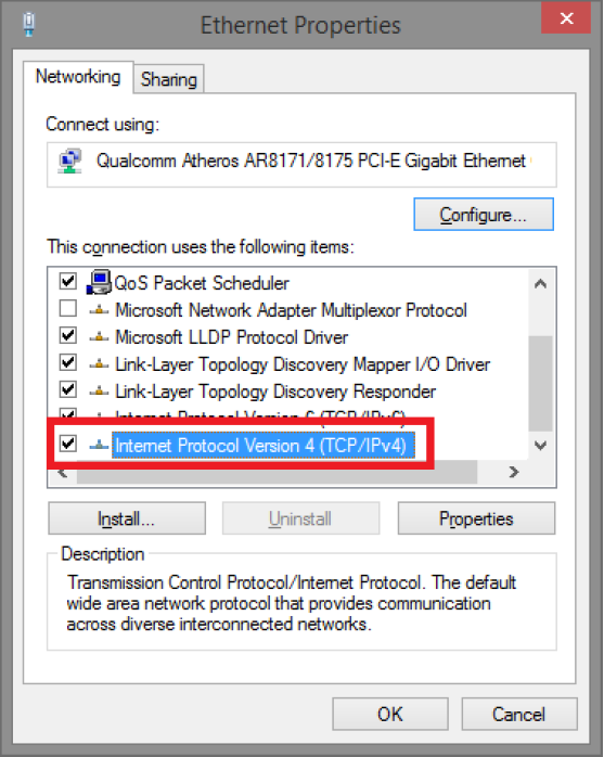
Double-click: Internet Protocol Version 4 (TCP / IPv4).
Set the computer's IP address and subnet mask as shown in the figure below. By default, the product's IP address be 192.168.2.1. You can set any IP address as long as it is not the same as your switch's IP address and is in the same network segment as your switch's IP address. Press on OK to apply the TCP/IPv4 settings you just made. Now you can connect to your switch using a web browser (Chrome, Edge or Firefox).
Connect an RJ-45 cable and connect to the PoE switch.
Log in to the PoE switch
Note
IP address of the switch (factory setting): 192.168.2.1
Password (factory setting): admin
Note
If you get a warning that the page is not secure/the connection is not private, click "advanced" and then "continue".
Start the browser on your computer.
Login to PoE switch.
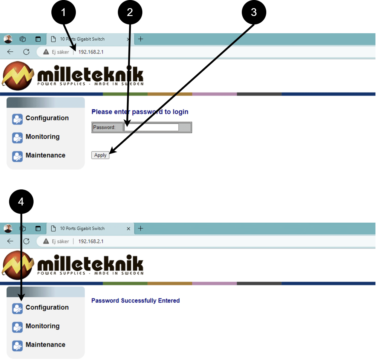 Table 7. Log in to the switch.
Number
Explanation
1
IP address of the PoE switch: 192.168.2.1
2
Password: admin
3
Apply = Ok
4
Menu in the PoE switch
Configuration
System, configuration
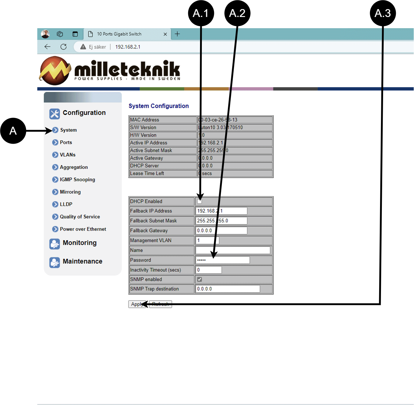
Letter, number | Explanation |
|---|---|
A | PoE switch system configuration page |
A.1 | Tick here if you are going to use DHCP, see warning below. |
A.2 | Changes the factory default password, (admin). |
A.3 | If you have made any changes, you need to click "Apply" to save the changes. |
Ports, configuration
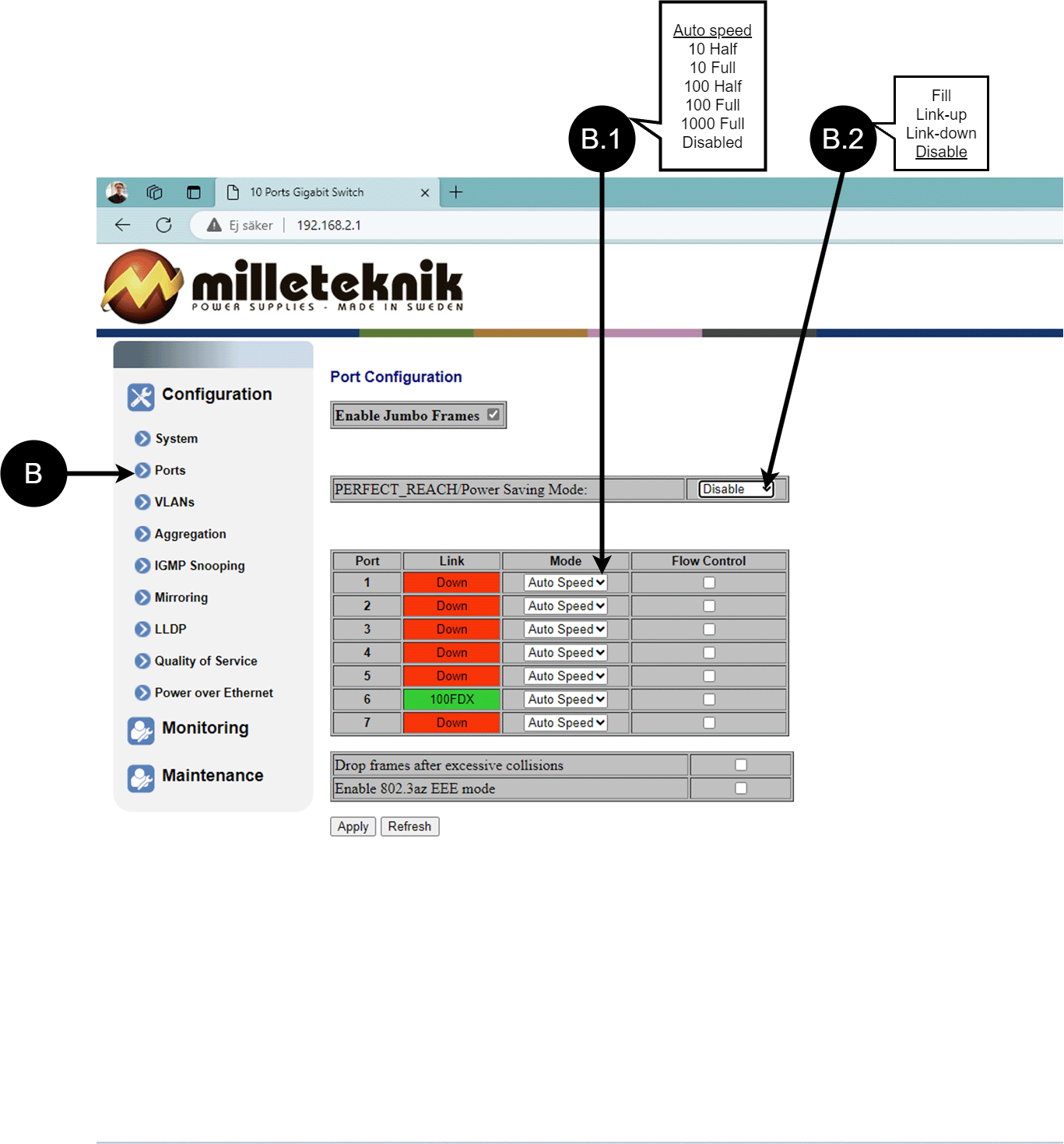
Letter, number | Explanation |
|---|---|
B | Gates |
B.1 | This setting normally does not need to be changed. Select the speed of the PoE switch's ports. |
B.2 | This setting normally does not need to be changed. |
VLAN configuration
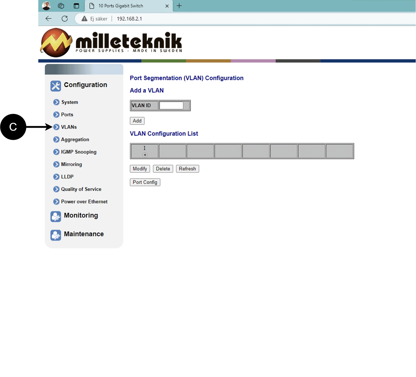
C: Configuration of Virtual LAN.
Aggregation, configuration
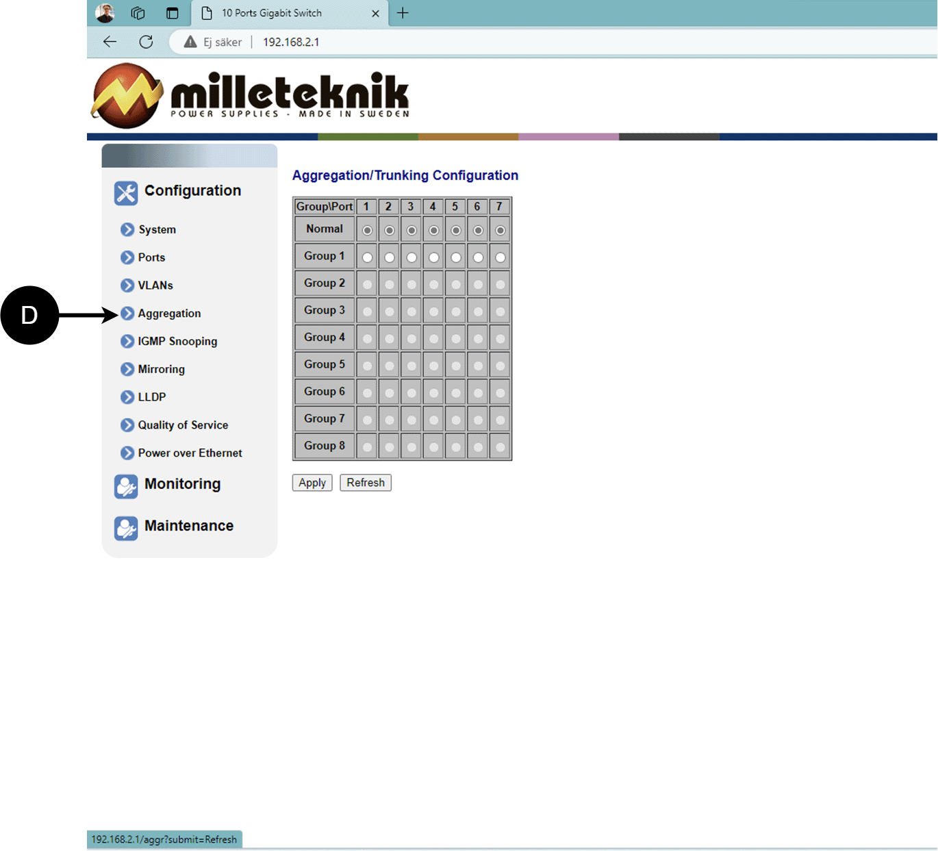
D: Load balancing between the ports.
IGMP Snooping, configuration
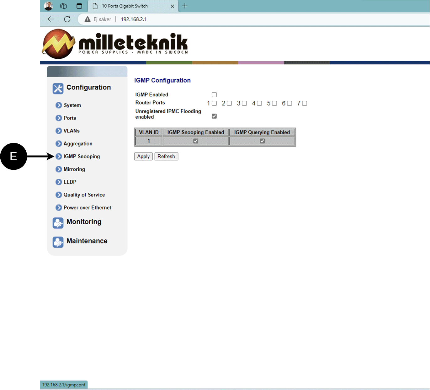
E: Switch that controls reception.
Mirroring, configuration
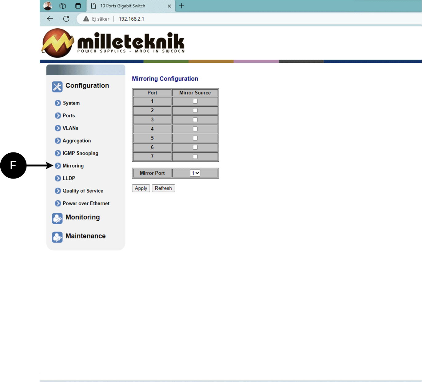
F: Mirroring of ports.
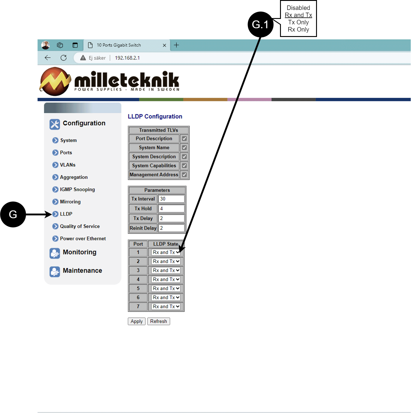
LLDP configuration
Letter, number | Explanation |
|---|---|
G | LLDP stands for "Link Layer Discovery Protocol", which is a network protocol standard used to discover and communicate information about network devices connected to the same Ethernet network. The protocol allows devices such as switches and routers to send and receive messages containing information about the device's identification, capabilities, and connection topology. |
G.1 | RX and TX are abbreviations used in electronics, communications, and computer networking to indicate the direction of data flow between devices. RX: The abbreviation "RX" stands for "Receive" or "Reception". It indicates that the device is receiving data or signals from another device. When a device has an RX input, it means that it is designed to receive data or information from a transmitting device. TX: The abbreviation "TX" stands for "Transmit" or "Transmission". It indicates that the device is transmitting data or signals to another device. If a device has a TX output, it means that it is designed to transmit data or information to a receiving device. These abbreviations are especially common when it comes to data communication, such as in the context of network cables where there are specific RX and TX wires that allow for two-way communication between devices. |
QoS, configuration
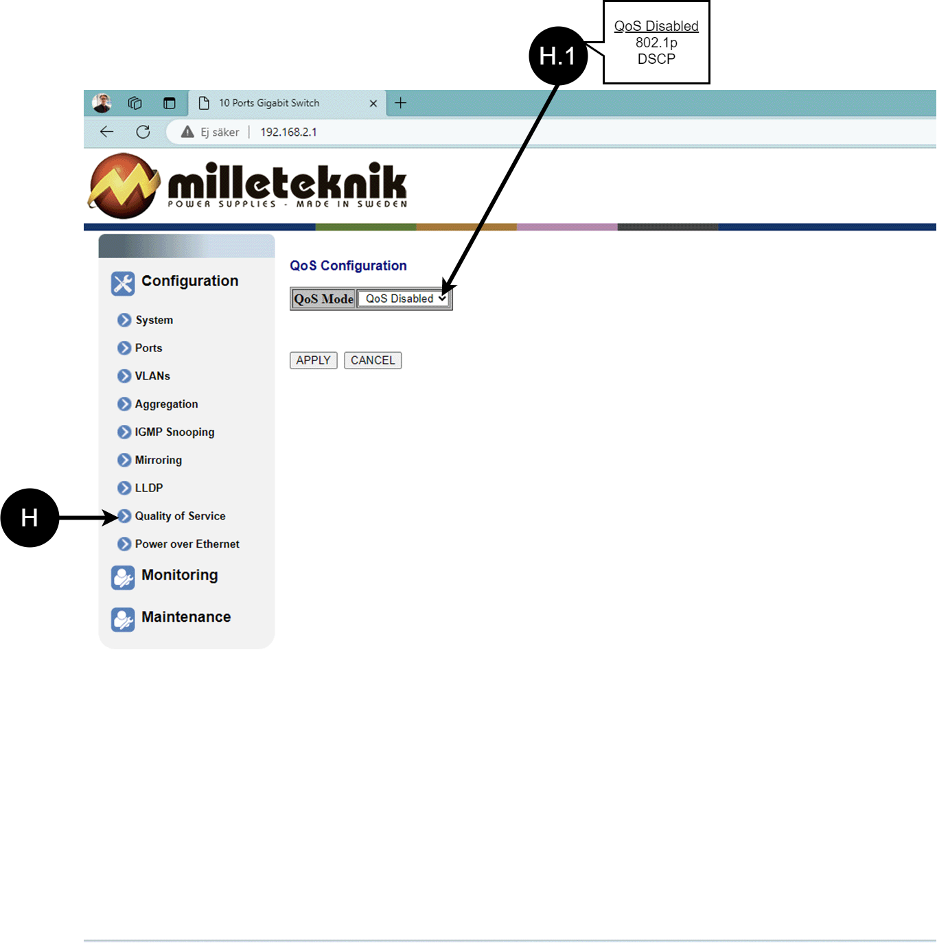
Letter, number | Explanation |
|---|---|
H | QoS gives different network traffic different priority, helping to ensure that important services are delivered with sufficient bandwidth and minimal delay even when the network is under load. |
H.1 | Sets whether QoS is active. |
PoE, configuration
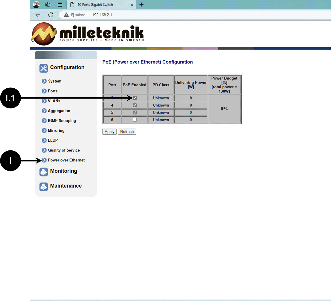
Letter, number | Explanation |
|---|---|
I | Power over Ethernet |
I.1 | Turns PoE function/port on or off. Remember to press "Apply" to save changes. |
Monitoring
Statistics, overview
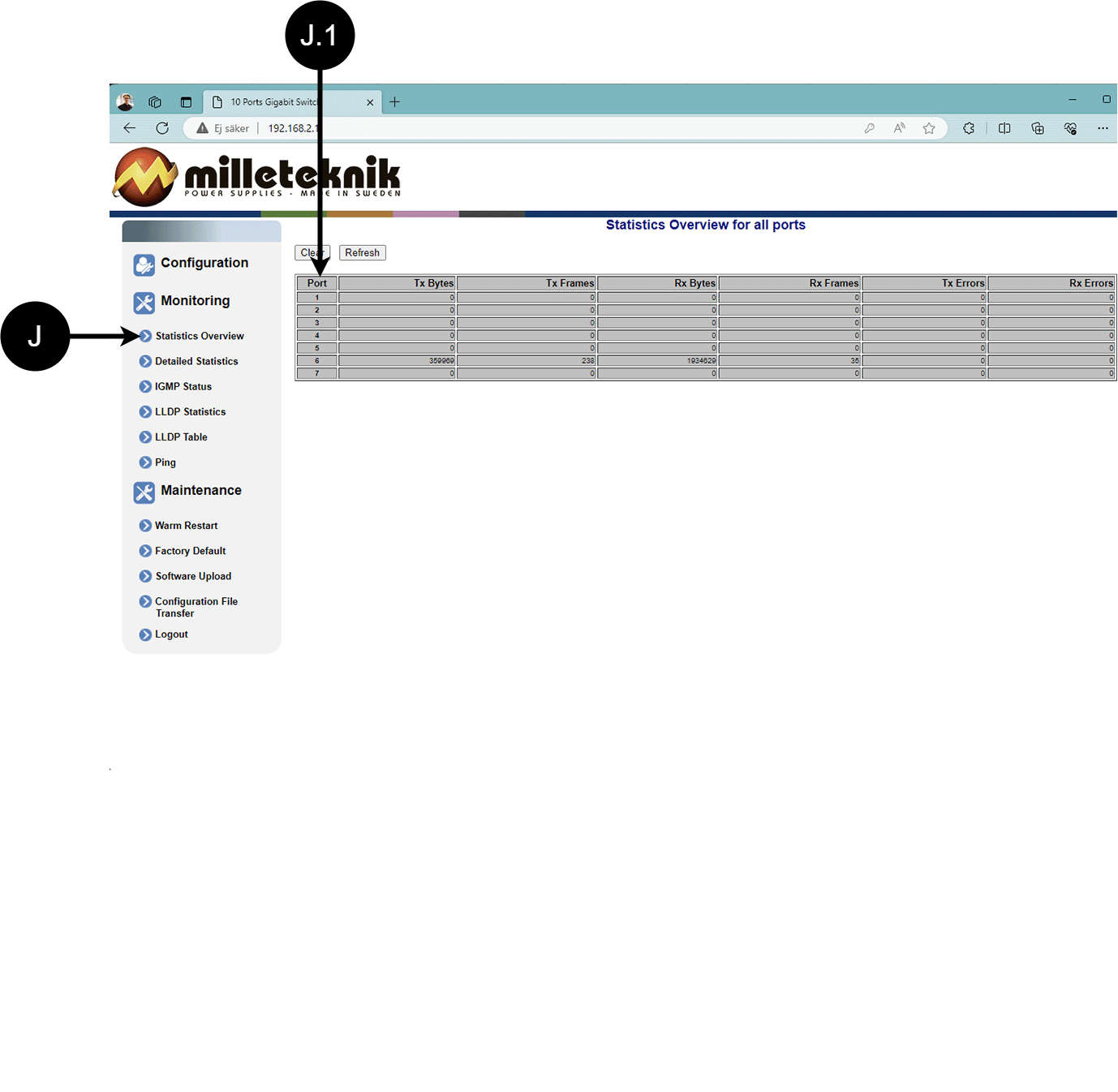
Letter, number | Explanation |
|---|---|
J | Statistics, overview |
J.1 | Traffic per port. |
Statistics, detailed
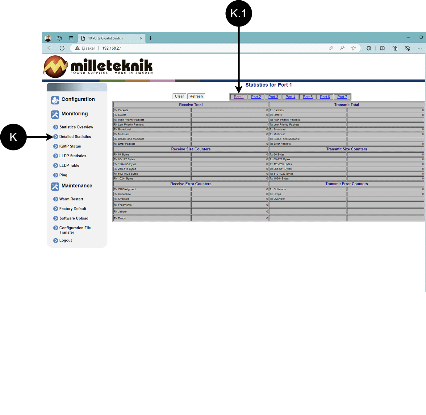
Letter, number | Explanation |
|---|---|
K | Detailed statistics |
K.1 | Select the port for which you want statistics. |
IGMP status
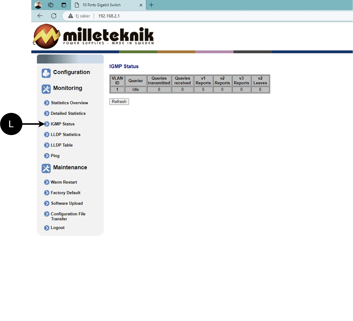
L: Status of IGMP
LLDP statistics
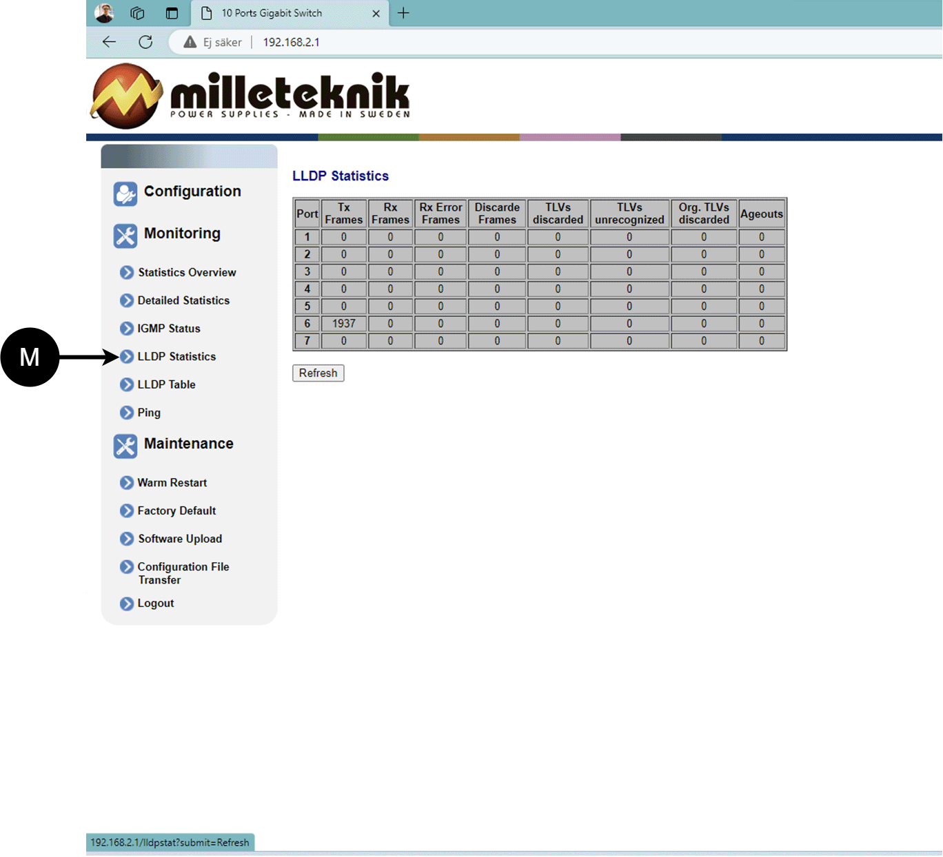
M: LLDP statistics
LLDP table
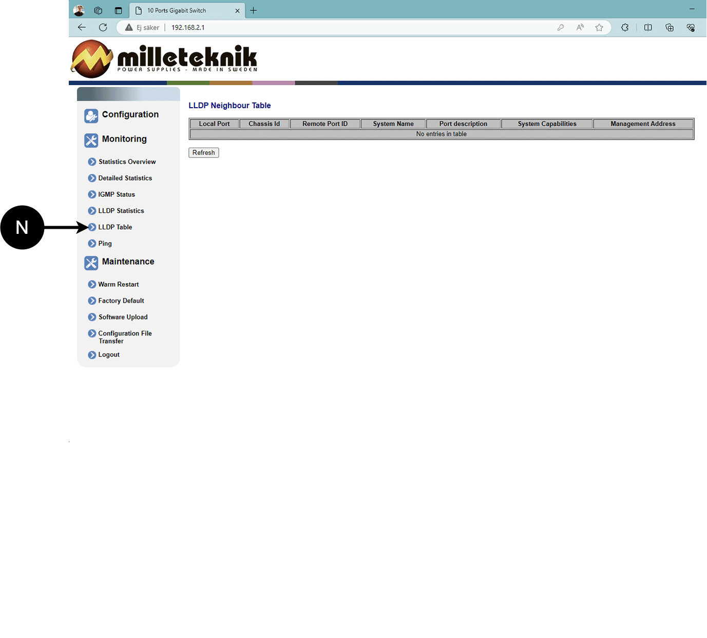
N: LLDP overview.
Ping
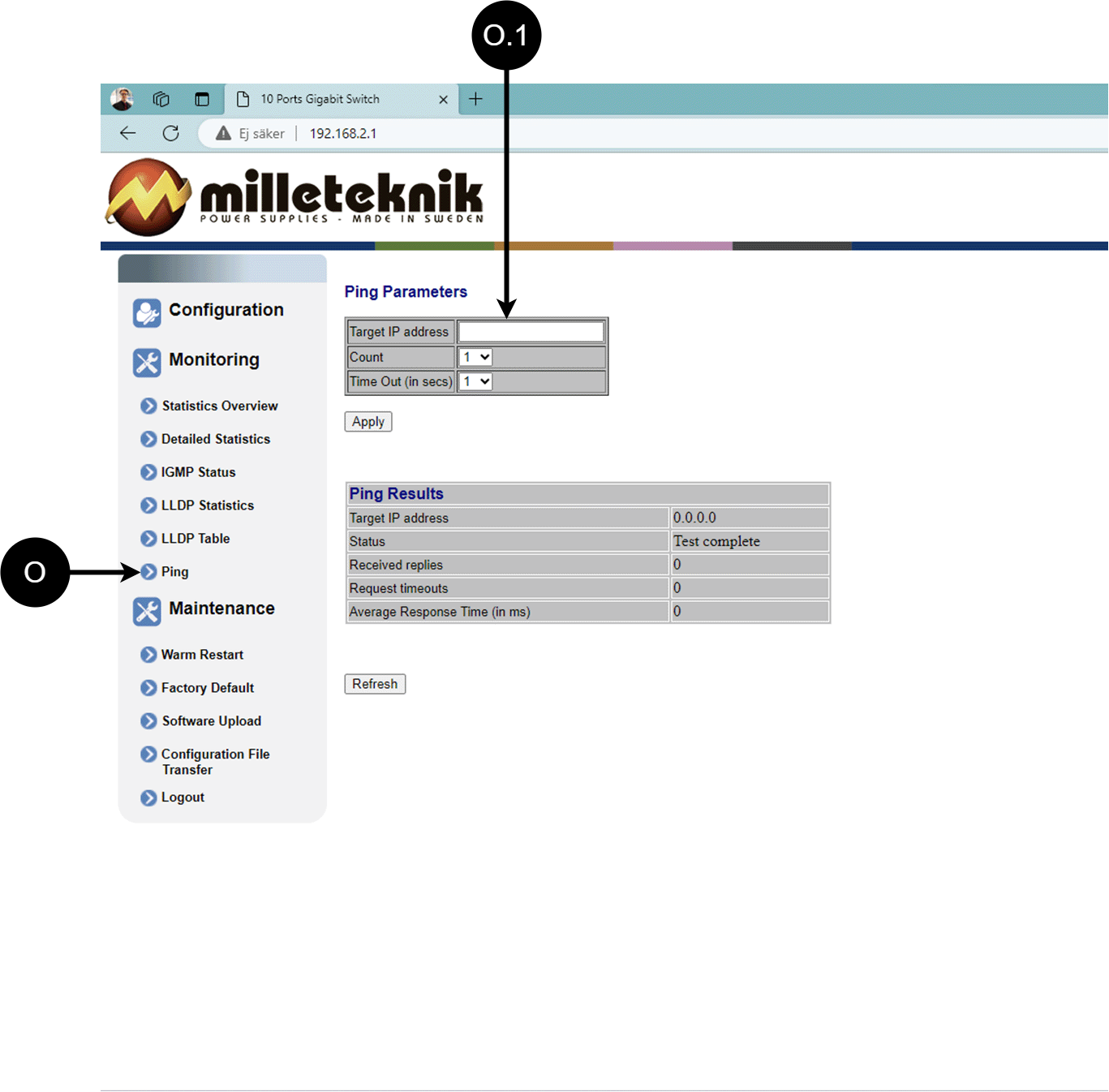
Letter, number | Explanation |
|---|---|
O | Ping |
[sv] O.1 | Input address to test the connection and response time. |
Maintenance
Reboot
Warning
Restart is done by PoE switch, battery backup is not restarted. Upon reboot, connected devices will lose connection. Alarm can be set to battery backup, but it disappears when the PoE switch is back on.
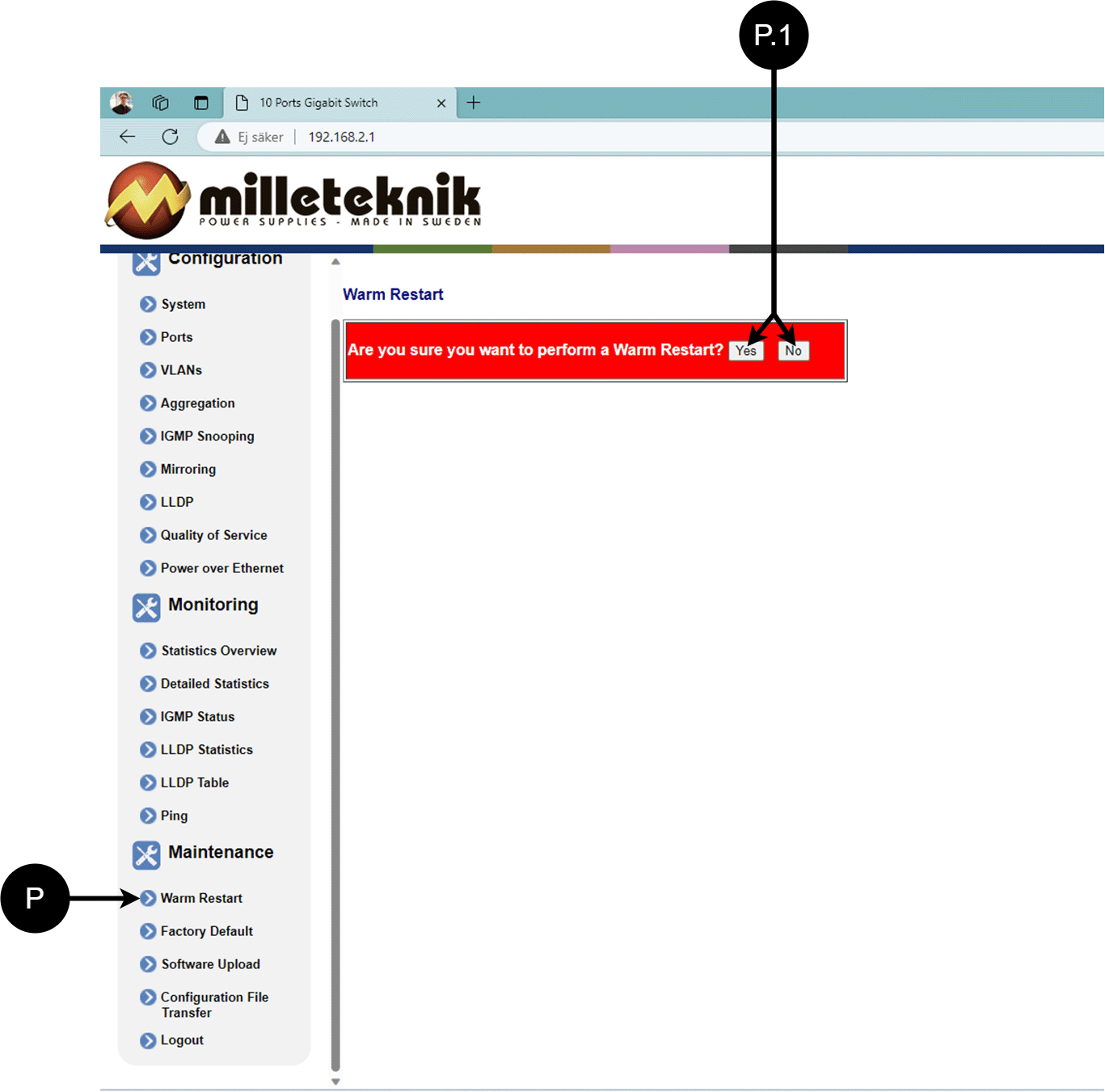
Letter, number | Explanation |
|---|---|
P | Rebooting the PoE switch. |
P.1 | Select "Yes" to reboot the switch. |
Factory reset
Warning
Factory reset is done by PoE switch. Battery backup is not restored. On reset, connected devices will lose connection. Alarm can be set to battery backup, but it disappears when the PoE switch is back on.
Factory reset of the switch can only be done from the software's (this) interface.
Recommendation: Keep IP address 192.168.2.1 and note password.
Important
During a factory reset, all settings, including IP settings, are lost. Save configuration before factory reset. See Upload new software
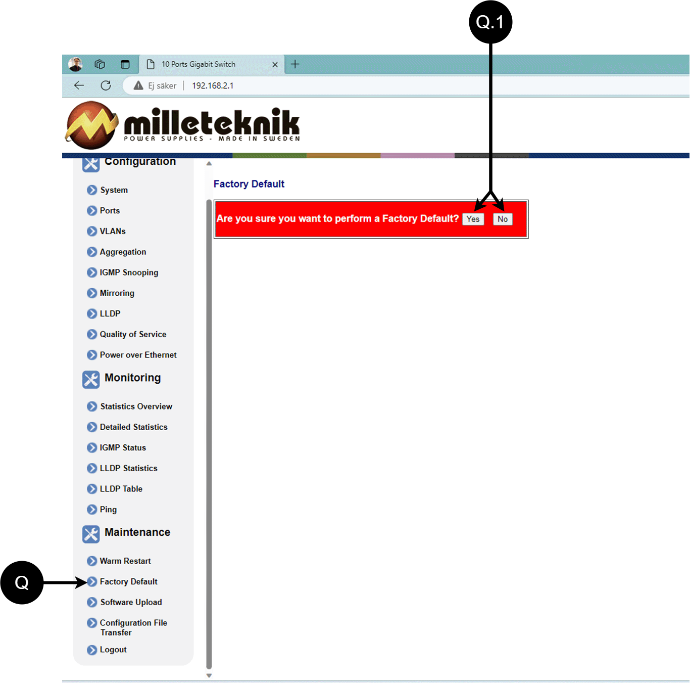
Letter, number | Explanation |
|---|---|
Q | Factory reset the PoE switch. |
Q.1 | Select "Yes" to factory reset the PoE switch. |
Upload new software
Warning
Only use software you received from Milleteknik's support. Milleteknik assumes no responsibility for software or consequences such as damage to the device or peripheral equipment or other damage that may arise from uploading unapproved software.
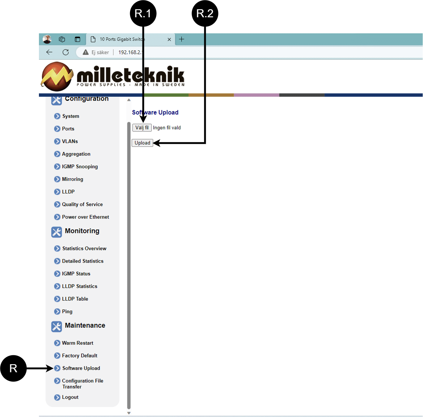
Letter, number | Explanation |
|---|---|
R | Upload new software to the Switch. |
R.1 | Navigate to the location on your computer where you saved the file. |
R.2 | Click "Upload" to upload the software. |
Load and save configuration file
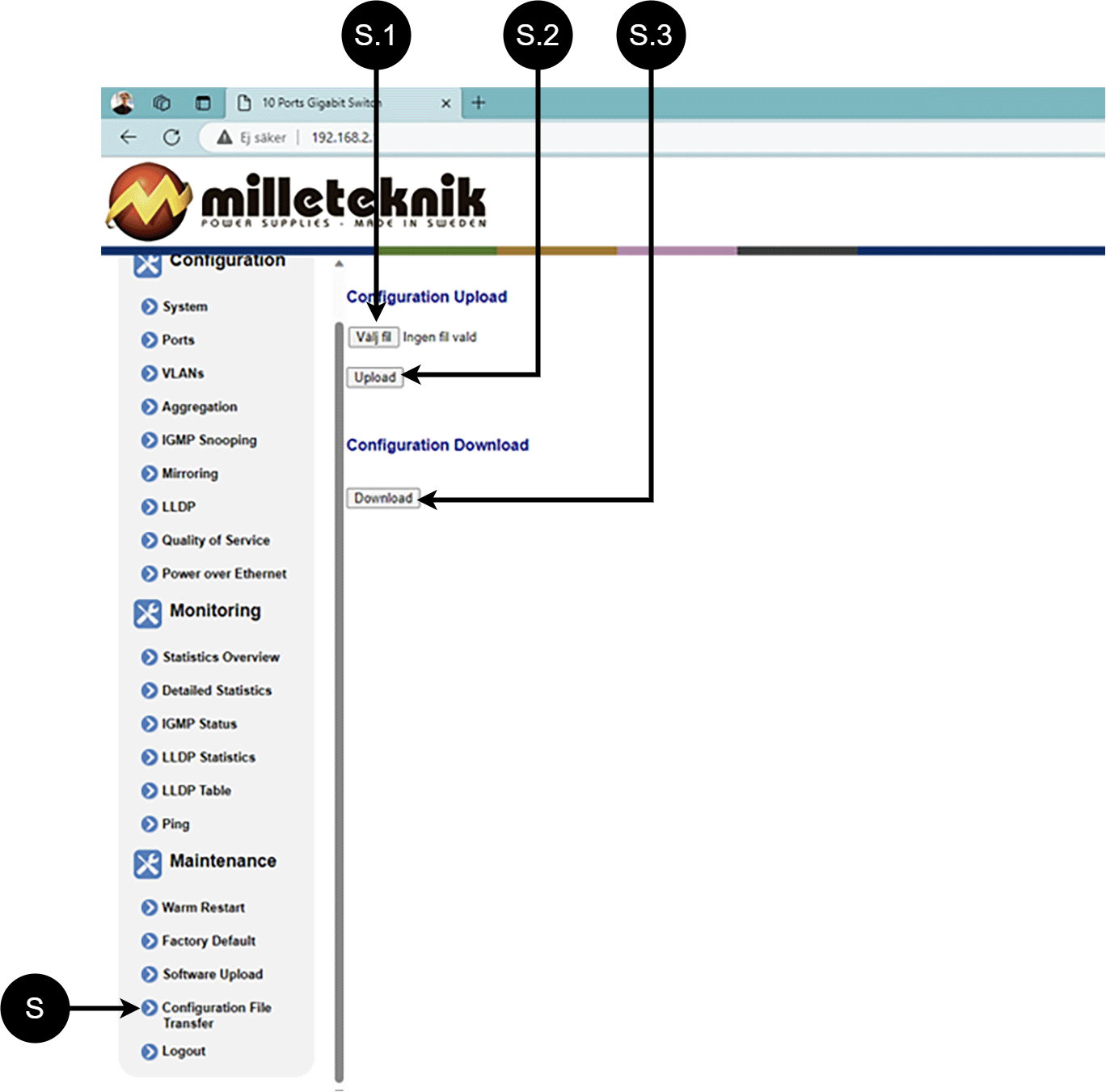
Letter, number | Explanation | ||||||||||||||||||||||||||||||||||||||||||||||||
|---|---|---|---|---|---|---|---|---|---|---|---|---|---|---|---|---|---|---|---|---|---|---|---|---|---|---|---|---|---|---|---|---|---|---|---|---|---|---|---|---|---|---|---|---|---|---|---|---|---|
S | Upload or download the switch's configuration. | ||||||||||||||||||||||||||||||||||||||||||||||||
S.1 | Select new configuration file. | ||||||||||||||||||||||||||||||||||||||||||||||||
S.2 | Upload new configuration file. | ||||||||||||||||||||||||||||||||||||||||||||||||
S.3 | Download configuration file to computer[a]. | ||||||||||||||||||||||||||||||||||||||||||||||||
[a] Newer Windows computers do not allow *.cfg files to be downloaded without additional approval in the browser when downloading. Antivirus programs may delete the file during download. | |||||||||||||||||||||||||||||||||||||||||||||||||
Sign out
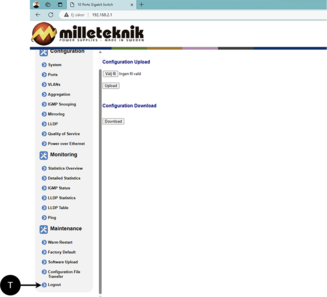
T: Log out of the switch. This does not affect the operation of the switch.
About this information
Specifications are subject to change without notice. Milleteknik accepts no liability for typographical errors. Information is updated without prior notice. |
Publication date 2026-10-05
Deployment - how to start the device
Danger
Personal injury or death can occur if the device is connected to the mains or live when disassembling / moving.
Connect load.
Connect batteries.
Connect mains voltage.
Plug in mains voltage.
Maintenance
The system, with the exception of fans and batteries, is maintenance-free. Check fans annually. Fan should rotate smoothly without any noise. Clean the fan from dust and dirt. The fan should be replaced if it does not rotate smoothly or is so dirty that it cannot be completely cleaned. If the fan does not work well, the air flow in the unit will be obstructed, as a result of which heat will increase in the housing, it will lead to the deterioration of battery life and thus the replacement interval of batteries will be significantly shortened
Product sheet - power supply / battery backup
Product Sheet
PoE
Product Identification
Product designation | Part number | E-number (SE) |
|---|---|---|
PoE Managed 4p 24V 5A UT S | PL02P30024P050P-UTS | 51 731 57 |
Description
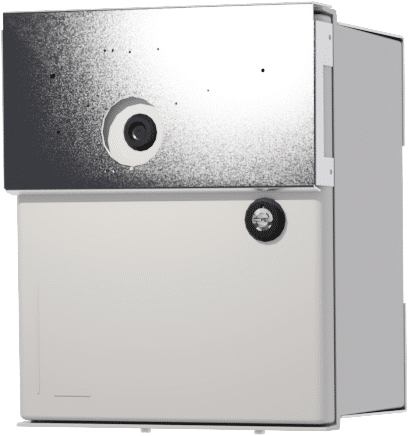
Outdoor PoE power supply, 24 V, 5 A, with space for two 14 Ah batteries.
Area of use
Power supply with backup power to power PoE devices such as surveillance cameras, 3-5G routers and has a 24 V output to be able to power other alarm components. Remote monitoring and control of PoE ports is possible. Batteries are located in a heated, thermostatically controlled and insulated part of the enclosure.
Power supply to power PoE devices such as surveillance cameras and other PoE powered devices.
Long life, energy efficient and support is available if something goes wrong, now or in 10 years.
Common uses
Supports IP cameras, readers, door centers and other networked security devices
Power and data distribution over a single network cable for simplified installation.
Used to power IP-based access systems where both data and power go through network cabinets.
Technical description
Contains a 4-port managed Gbit PoE+ switch with 30.8W per port, a total of 150W including battery recharge. Can be managed over VPN[1] for control and status monitoring including power consumption per port. Equipped with total alarm and 24V output from the backup for operation of other equipment. Thermostatically controlled, insulated compartment for batteries and temperature sensor for protection against overcharging. Works in temperatures from -15°C to +35°C, IP65 rated. Prepared for mounting on a pole and prepared for logger function for collecting data.
Voltage, current and power
Mains voltage: 230 V AC - 240 V AC, 47 Hz - 63 Hz.
Load outputs
PoE switch can drive load to PoE devices and motherboard can drive one (1) 24V load output to drive other applications.
Alarm
Alarms are given for: Delayed power failure alarm or low battery voltage, disconnected batteries, fuse failure and overcharging of batteries.
Alarm over RJ-45, see manual for alarms that PoE switch can give.
Protection
Protection against overload, overvoltage, overtemperature, short circuit and deep discharge.
Fuses
Mains fuse: 2.5 A.
Battery protection: 16 A and 30 A.
Battery and battery type
Battery type: 12 V, AGM lead-acid battery, maintenance-free. Battery sizes must not be mixed.[2].
2 pieces 7.2 Ah battery.
Backup operating time on batteries
The reserve operating time in battery operation depends on how large a load is connected to the power supply. If the load varies, as with frequent opening of door locks, the time that batteries can continue to power the security system decreases. To get an estimate of reserve operating times see: www.milleteknik.se/Manualer/FaQ/Reservdrifttider/
Enclosure
Box in fiberglass reinforced acrylic plastic.
Weight
Name | Net weight | Weight incl. packaging |
|---|---|---|
PoE Managed 4p 24V 5A OUT S | 11.45 kg | 12.2 kg |
Installation requirements
The device is intended for fixed installation. Ambient temperature: – 15°C to +35°C.
Requirements that the product meets
EMC: | EMC Directive 2014/30/EU |
Electricity: | Low Voltage Directive 2014/35/EU |
CE marking: | Regulation (EC) No 765/2008 |
Emissions: | |
Immunity: | EN61000-6-2:2005, EN61000-4-2, -3, 4, -5, -6, -11 SS-EN 50 130-4:2011 Edition 2, EN50131-6 |
Machinery Directive | The product is part of electrical systems, is subject to the relevant electrical and safety directives and is not a machine according to the Machinery Directive (2006/42/EC). |
Ecodesign | Milleteknik's products are intended for professional use and are therefore not directly covered by the Ecodesign Regulation (EU 2019/1782). As some components may be covered, we nevertheless disclose relevant information to give our customers confidence in their choice |


Guarantee
Manufacturing, lifespan, environmental impact and recycling
Manufactured by Milleteknik in Partille, Sweden.
Link to technical specifications
Links to manuals and product sheets
You can find manuals and product sheets at: www.milleteknik.se The QR code below takes you to the product page.
Name | Dimensions | Batteries that fit | Link |
|---|
Batteries are only included if specified, otherwise batteries will need to be purchased separately.
Miscellaneous
The difference between PoE, PoE+ and PoE++.
About this information
Specifications are subject to change without notice. Milleteknik accepts no liability for typographical errors. Information is updated without prior notice. |
Publication date 2026-10-05
Address and contact details
Milleteknik AB |
Ögärdesvägen 8 B |
S-433 30 Partille |
Sweden |
+46 31 340 02 30 |
info@milleteknik.se |
www.milleteknik.com |
[1] VPN requires externally connected hardware and software (PC) connected to the PoE switch.
[2] The number of batteries listed represents the maximum number that the device can handle at the same time. If multiple battery sizes are specified, this means that the device can only accommodate one battery size at a time.
[3] Costs incurred in connection with recycling are not reimbursed.