Area of use
For applications that require a different output voltage than that supplied by the battery backup or power supply. Allows flexible adaptation to different operating voltages to drive, for example, control boards, locks, sensors or other electronics that are not compatible with the system's regular output
Name, article number and e-number
Name | Item number | E-number (sv) |
|---|---|---|
Voltage-converter WR | A-VC002404A04LM01 | 5213774 |
Installation and commissioning
Instructions for installation and commissioning.
Mounting in battery backup
The card is delivered mounted in it's plastic casing, for easy installation.
Mount the card on any card slot in the enclosure, leave space for cables.
Important
Install the board before screwing on wiring or commissioning.
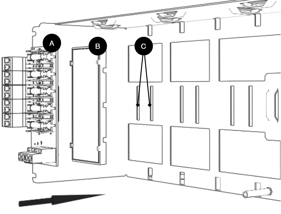
Letter | Explanation | Comment |
|---|---|---|
A | Optional card | Optional card comes mounted on plastic housing from factory. Has it come loose? Snap it back on before mounting the card. |
B | Plastic casing | The plastic casing has hooks for attaching slots in the plate. |
C | Place for plastic casing | Slits in sheet metal. |
Short description
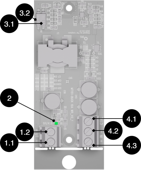
No. | On circuit boards | Explanation |
|---|---|---|
1.1 | OUT- | Voltage out - (minus). |
1.2 | UT+ | Voltage out + (plus). |
2 | STATUS | Status LED, lights green when voltage is on UT, (1.1-1.2). |
3.1 | S1 | Dip switch 1 to set voltage out. See table. |
3.2 | S1 | Dip-switch 2 to set voltage out. See table. |
4.1 | CTRL | Control signal for voltage IN. Through external switch, voltage input can be checked: ON/OFF |
4.2 | IN - | Voltage in - (minus). |
4.3 | IN + | Voltage in + (plus) |
Voltage out | Location dip1 | Mode dip2 |
|---|---|---|
5V (5.1V) | HE | HE |
6V (5.9V) | HE | OFF |
12 V (12.6 V) | OFF | HE |
24 V (24.9 V) | OFF | OFF |
Example: For 12 V out, mode should be | OFF | HE |
Switching load
Connect to motherboard CEO 3
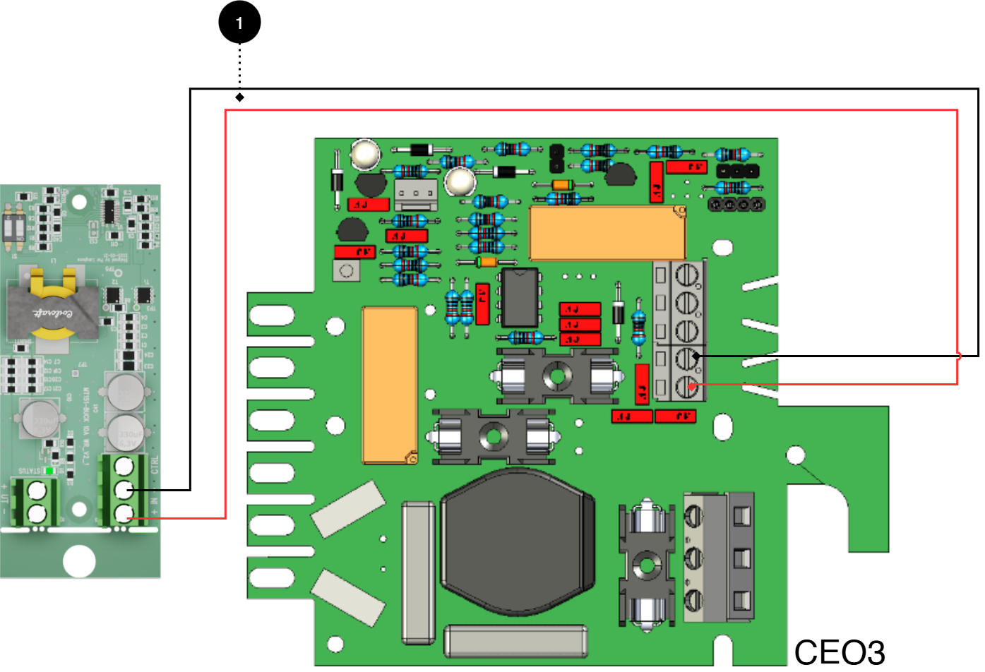
No. | Explanation |
|---|---|
1 | Connect plus and minus from load output on motherboard to plus and minus. |
Connect to motherboard CEO 3 v5
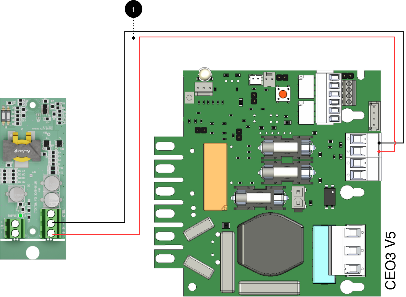
No. | Explanation |
|---|---|
1 | Connect plus and minus from load output on motherboard to plus and minus. |
Connect to motherboard NEO3
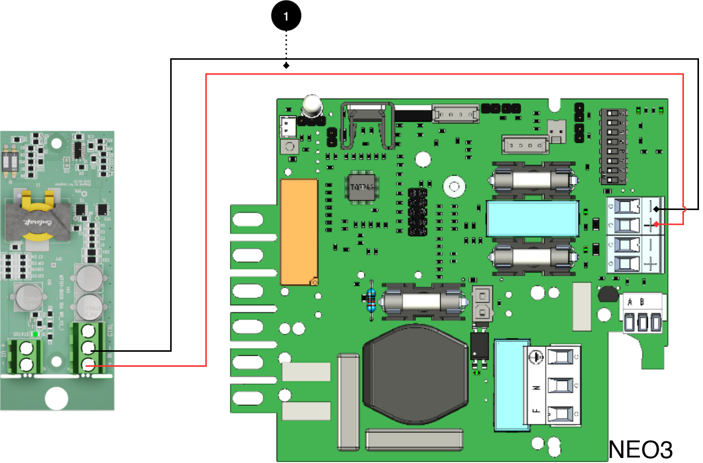
No. | Explanation |
|---|---|
1 | Connect plus and minus from load output on motherboard to plus and minus. |
Connect to motherboard PRO1 5A-10A
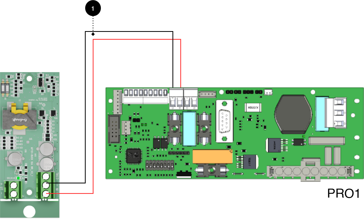
No. | Explanation |
|---|---|
1 | Connect plus and minus from load output on motherboard to plus and minus. |
Connect to motherboard PRO1 15A-25A
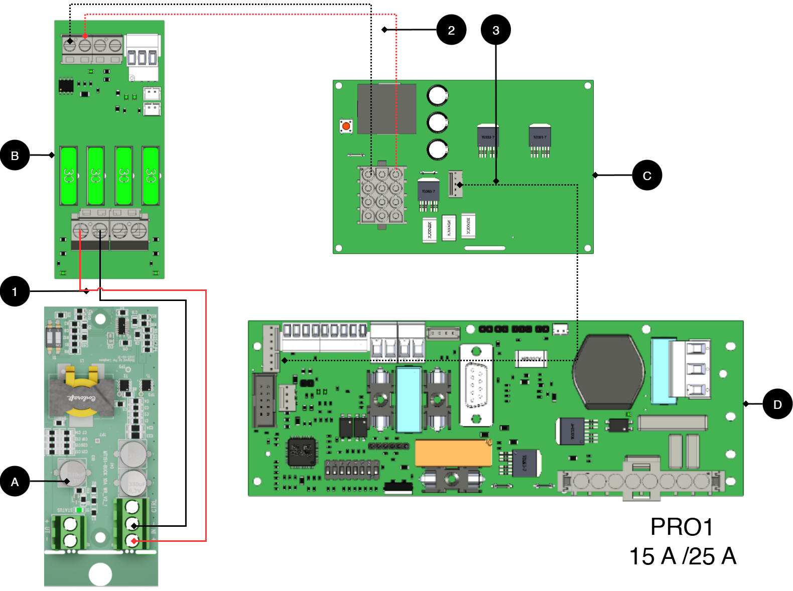
Letter | Circuit Boards |
|---|---|
A | Voltage converter WR 48.24, 12V |
B | Cargo card |
C | Power card |
D | Motherboard |
No. | Explanation |
|---|---|
1 | Connect the plus and minus from load output on load card to plus and minus. |
2 | Internal connection from power board to load board. |
3 | Internal connection from power board to load board. |
Connect to motherboard PRO2v3 5A-10A
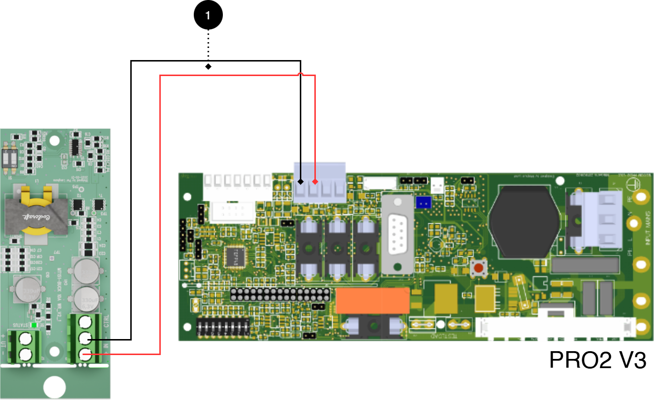
No. | Explanation |
|---|---|
1 | Connect plus and minus from load output on motherboard to plus and minus. |
Connect to motherboard PRO2 v3 15A-25A
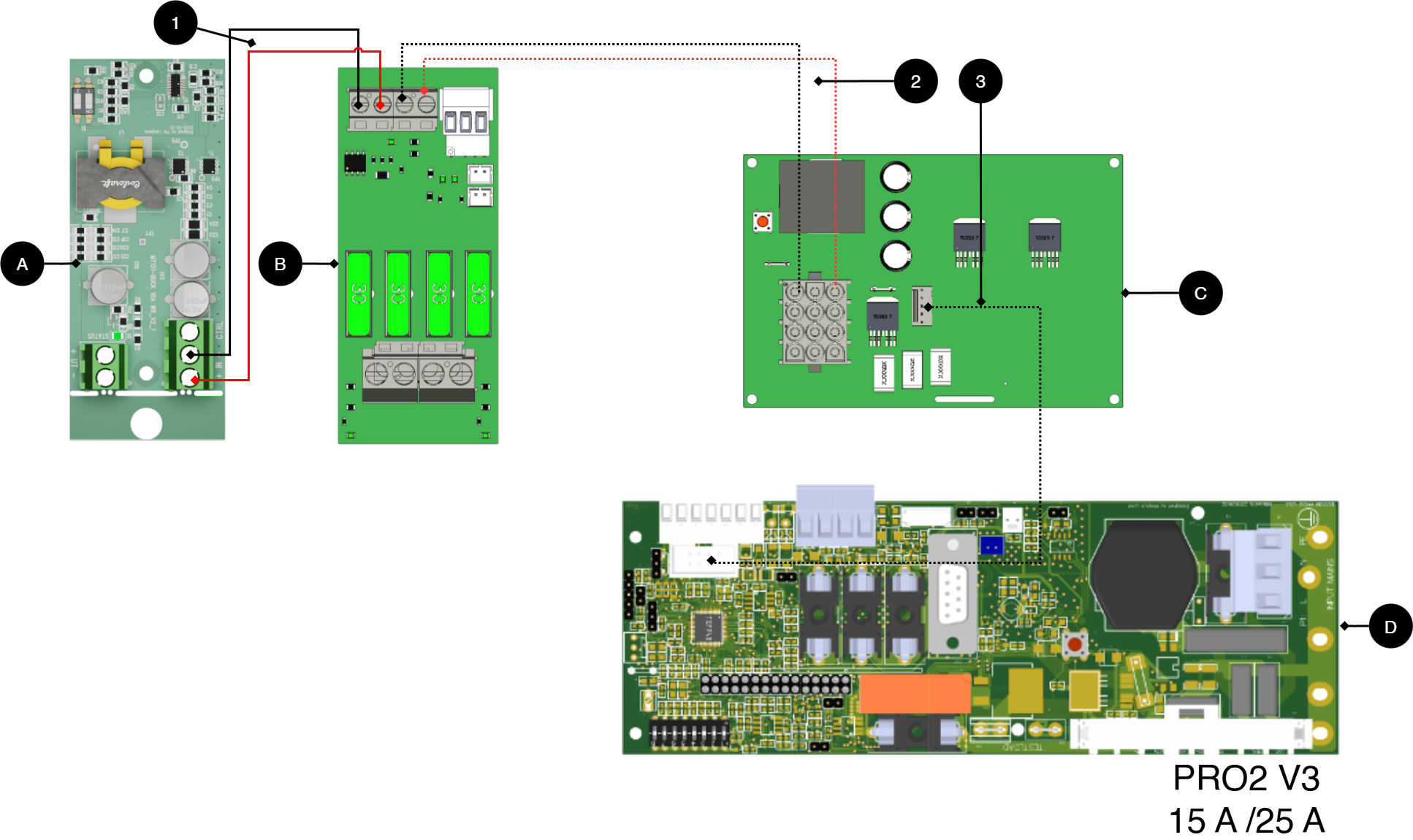
Letter | Circuit Boards |
|---|---|
A | Voltage converter WR 48.24, 12V |
B | Cargo card |
C | Power card |
D | Motherboard |
No. | Explanation |
|---|---|
1 | Connect the plus and minus from load output on load card to plus and minus. |
2 | Internal connection from power board to load board. |
3 | Internal connection from power board to load board. |
Connect to motherboard PRO3 5A-10A
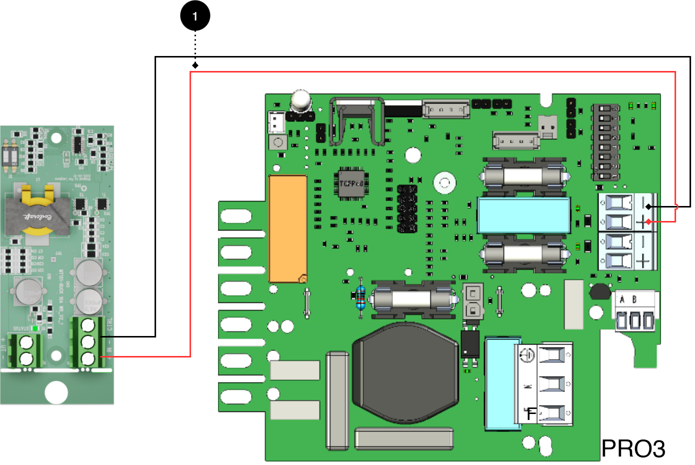
No. | Explanation |
|---|---|
1 | Connect plus and minus from load output on motherboard to plus and minus. |
Product sheet - power supply / battery backup
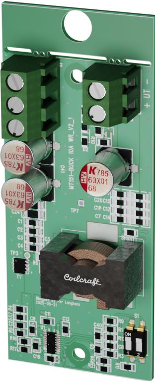
Product Sheet
Product image
Name, article number and e-number
Name | Item number | E-number (sv) |
|---|---|---|
Voltage-converter WR | A-VC002404A04LM01 | 5213774 |
Technical description
[sv] DC/DC-omvandlare med styrning och för konvertering till lägre spänningsnivå (24 V DC, 12 V DC, 6 V DC och 5 V) i Milletekniks strömförsörjningssystem. Kortet monteras som tillval och möjliggör flexibel anpassning av utspänning samt larmåterkoppling till överordnat system. Styrning: CTRL -> GND = OFF.
[sv]
[sv]
Quick Facts | |
|---|---|
Supply voltage (V) | [sv] 48, 24, 12 V DC. |
Voltage out (V) | [sv] 24, 12, 6, 5 V DC. |
Accessories for | Outdoor Enclosures. |
Areas of application
Areas of application | Yes | No |
|---|---|---|
[sv] Används där annan, lägre, spänningsnivå krävs för att driva exempelvis dörrläsare, lås och andra anslutna enheter | ✔ |
Electronics
[sv] Elektriska data | |
|---|---|
[sv] Matningsspänning | [sv] 48, 24, 12 V DC. |
[sv] Standbyförbrukning | [sv] 0,53 W |
[sv] Spänning ut | [sv] 24, 12, 6, 5 V DC. |
Circuit Boards | Internal power consumption | Other. info |
|---|---|---|
Voltage converter 48 24V 12V WR | Data is missing. |
Load outputs
Load outputs | |
|---|---|
Number of load outputs |
|
Alarm and protection
Communication and Indications
Communication and Indications | Yes | No | Other. info. |
|---|---|---|---|
Communication | ✘ | ||
Alarm feedback to power supply | ✔ | ||
Indicators/LEDs | ✔ |
|
Enclosure and Mechanics
Enclosure and Mechanics | |
|---|---|
Enclosure | Does not have enclosure |
Assembly, installation and eligibility requirements
Fitting | [sv] Ja | [sv] Nej |
|---|---|---|
In product (optionally fitted in compatible product). | ✔ |
Installation | Yes | No |
|---|---|---|
Installed in product. | ✔ |
Dimensions, weight and packaging information
Net weight | Weight with packaging |
|---|---|
0.2 kg | 0.4 kg |
Packaging | |
|---|---|
Packaging | Cardboard and impact protection in cardboard. |
Quantity in pack | 1 pc. |
Packaging Type (GS1 T0137) | BX box. |
Conditions EUR pallet | EUR pallets may not be stacked during transport or storage. Stacking may result in damage to product and packaging |
Transport environment | The product must be protected from condensation and direct precipitation during transportation. |
Transport temperature (without battery) | −30 °C to +70 °C |
Storage environment | Dry indoor environment, protected from condensation. Relative humidity: max 95%, non-condensing |
Storage temperature without batteries | −20 °C to +60 °C |
The accessories fits in
Contact
Department | |
|---|---|
Switchboard | 031-340 02 30 |
Support and technical issues | support@milleteknik.se |
Sales | sales@milleteknik.se |
WWW | www.milleteknik.se |
Address | Ögärdesvägen 8B, 433 30 Partille |
About this information
All information is published subject to possible errors. Information is updated without prior notice. |
Publication date 2026-06-24
[sv] Compliance och regelefterlevnad
Delivery time, warranty and terms
Delivery time, warranty and terms | |||||||||||||||||||||||||||||||||||||||||||||||||
|---|---|---|---|---|---|---|---|---|---|---|---|---|---|---|---|---|---|---|---|---|---|---|---|---|---|---|---|---|---|---|---|---|---|---|---|---|---|---|---|---|---|---|---|---|---|---|---|---|---|
Warranty period[a] | [sv] Produkten har två (2) års garanti mot tillverkningsfel. | ||||||||||||||||||||||||||||||||||||||||||||||||
Special warranty conditions | See also general terms and conditions. | ||||||||||||||||||||||||||||||||||||||||||||||||
General Terms and Conditions | ALEM09 with exceptions, see: www.milleteknik.se/conditions/ | ||||||||||||||||||||||||||||||||||||||||||||||||
Support | Telephone support and email support during the warranty period are free of charge. For spare parts that are not covered by warranty, there is a charge | ||||||||||||||||||||||||||||||||||||||||||||||||
Delivery and stock | |||||||||||||||||||||||||||||||||||||||||||||||||
Delivery time[b] | 5 working days. Or as per agreement. Delivery from factory, transportation time is added. | ||||||||||||||||||||||||||||||||||||||||||||||||
[a] If the device is purchased through a wholesaler or other supplier, other warranty conditions may apply [b] In the case of larger orders, delivery time increases, acc. to agreement. | |||||||||||||||||||||||||||||||||||||||||||||||||
Operation and maintenance
Operation | Data | Other. info | |||||||||||||||||||||||||||||||||||||||||||||||
|---|---|---|---|---|---|---|---|---|---|---|---|---|---|---|---|---|---|---|---|---|---|---|---|---|---|---|---|---|---|---|---|---|---|---|---|---|---|---|---|---|---|---|---|---|---|---|---|---|---|
Environment | Indoor environmental class 1. | ||||||||||||||||||||||||||||||||||||||||||||||||
Operating temperature (recommended) | +15°C to +25°C | ||||||||||||||||||||||||||||||||||||||||||||||||
Operating temperature (permissible)[a] | +5°C to +40°C | Class 1 according to EN 50131-6/ EN 60839-11 | |||||||||||||||||||||||||||||||||||||||||||||||
[a] Specifies the permissible ambient temperature range in which the product can operate without damage. See also table on battery life. | |||||||||||||||||||||||||||||||||||||||||||||||||
Yes | No | Interval | Other. info |
|---|---|---|---|
✔ | Maintenance-free. |
Certifications and approvals
Complies with | Directives |
|---|---|
C.E. | CE marking according to (EC) 765/2008 |
EMC | EMC Directive 2014/30EU |
Electric (LVD) | Low Voltage Directive: 2014/35/EU |
Environmental data
Environmental data | J/N | Informație | Other. info. | ||||||||||||||||||||||||||||||||||||||||||||||
|---|---|---|---|---|---|---|---|---|---|---|---|---|---|---|---|---|---|---|---|---|---|---|---|---|---|---|---|---|---|---|---|---|---|---|---|---|---|---|---|---|---|---|---|---|---|---|---|---|---|
Building Product Declaration (BPD) | ✔ | Yes, see iBvd at www.milleteknik.se. | - | ||||||||||||||||||||||||||||||||||||||||||||||
REACH Information Obligation (EC) No 1907/2006 | ✔ | Yes, see the DoC at www.milleteknik.se The product complies with REACH Regulation (EC) No 1907/2006. | If empty, the product is not covered. | ||||||||||||||||||||||||||||||||||||||||||||||
SVHC substances, CAS/EC | ✔ | Yes, lead, 7439-92-1/231-100-4 | For text, see iBvd at www.milleteknik.se. If blank, substance is missing. | ||||||||||||||||||||||||||||||||||||||||||||||
Subject to the RoHS Directive, (EU) 2015/863) | ✔ | Yes, see the DoC at www.milleteknik.se | |||||||||||||||||||||||||||||||||||||||||||||||
WEEE 2012/19/EU | ✔ | The product contains electrical components or wiring and is covered by the WEEE Directive (2012/19/EU). | If empty, the product is not covered. End-of-life products must be returned to a recycling centre | ||||||||||||||||||||||||||||||||||||||||||||||
Battery Regulation (EU) 2023/1542 | ✗ | ||||||||||||||||||||||||||||||||||||||||||||||||
SCIP No 2008/98/EC | ✔ | Yes, registered under the EU Waste Directive where applicable, (2008/98/EC). | If empty, no SCIP number is needed. | ||||||||||||||||||||||||||||||||||||||||||||||
Conflict minerals (EU) 2017/821 | ✗/✗/✗/✗/✔ | No=Gold, Tungsten, Tantalum, Cobalt. Yes=Tin | [sv] Tenn i lödningar i kretskort som köps in via svensk leverantör. | ||||||||||||||||||||||||||||||||||||||||||||||
Contains nanomaterials: EC 1272/2008 | ✗ | The product does not contain nanomaterials. | |||||||||||||||||||||||||||||||||||||||||||||||
Ecodesign 2009/125/EC | Milleteknik's products are intended for professional use and are therefore not directly covered by the Ecodesign Regulation (EU 2019/1782). As some components may be covered, we nevertheless disclose relevant information[a], where applicable, to provide our customers with confidence in their choice. | ||||||||||||||||||||||||||||||||||||||||||||||||
Machine Directive 2006/42/EC | The product is part of electrical systems, is subject to the relevant electrical and safety directives and is not a machine according to the Machinery Directive (2006/42/EC). Will be replaced by Machinery Regulation (EU) 2023/1230, which will apply in 2027. | ||||||||||||||||||||||||||||||||||||||||||||||||
[a] Standby consumption and power. | |||||||||||||||||||||||||||||||||||||||||||||||||

Manufacturer and country of origin
Manufacturer[a] | Milleteknik AB | ||||||||||||||||||||||||||||||||||||||||||||||||
Customs State. Nos. | [sv] 85044095[b] | ||||||||||||||||||||||||||||||||||||||||||||||||
Country of origin | Sweden | ||||||||||||||||||||||||||||||||||||||||||||||||
[a] Manufacturer is the trademark indicated on the product, regardless of what is stated in this product sheet. [b] Verifiera med tullombud/Tullverket vid export/import; alternativ klassificering 85044055 kan bli aktuell om produkten bedöms som ackumulatorladdare. | |||||||||||||||||||||||||||||||||||||||||||||||||
[sv] Bilaga
[sv] Behörighetskrav, installation
[sv] Krav på behörighet varierar mellan länder. Tabellen sammanfattar nationella krav för fast installation respektive anslutning av utrustning med stickkontakt.
Permission Requirements for Installation | Fixed installation (230 V) | Plug | Other. info |
|---|---|---|---|
Sweden | ✔ | ✗ | Fixed installation may be performed by technicians but shall be under the responsibility of a qualified installer. (Electrical Safety Act, SS 436 40 00) Plug may be connected without authorization. |
Norway | ✔ | ✔ | Requirements for qualified electricians also for equipment with a plug socket in fixed installations. (NEK 400, DSB |
Finland | ✔ | ✗ | Plug may be connected without authorization. (Tukes, SFS 6000 |
Denmark | ✔ | ✗ | Plug may be connected without authorization. (Safety Board |
Germany | ✔ | ✗ | All fixed installations require a qualified electrician according to VDE 0100. Plug sockets may be connected without authorization, but only by person with basic electrical knowledge (“Elektrotechnisch unterwiesene Person”) |
[sv] Referenstabell: miljöklasser enligt EN 50130-5 (som hänvisas till i EN 50131-6)
Class | Type | Temperature range |
|---|---|---|
Environmental Class 1 | Heated indoors (type office/residence). | +5°C to +40°C |
Environmental Class 2 | Generally indoors (type warehouses/stairwells, not temperature controlled). | -10°C to +40°C |
Environmental class 3 | Protected outdoors. | -25°C to +50°C |
Environmental class 4 | Generally outdoors. | -25°C to +60°C |
[sv] Referenstabell: tillverkares angivna livslängd och rekommenderat batteribyte
About this information
All information is published subject to possible errors. Information is updated without prior notice. |
Publication date 2026-06-24