Mounting
The card can be mounted in battery backup from the factory, in its own enclosure or sent as a loose card.
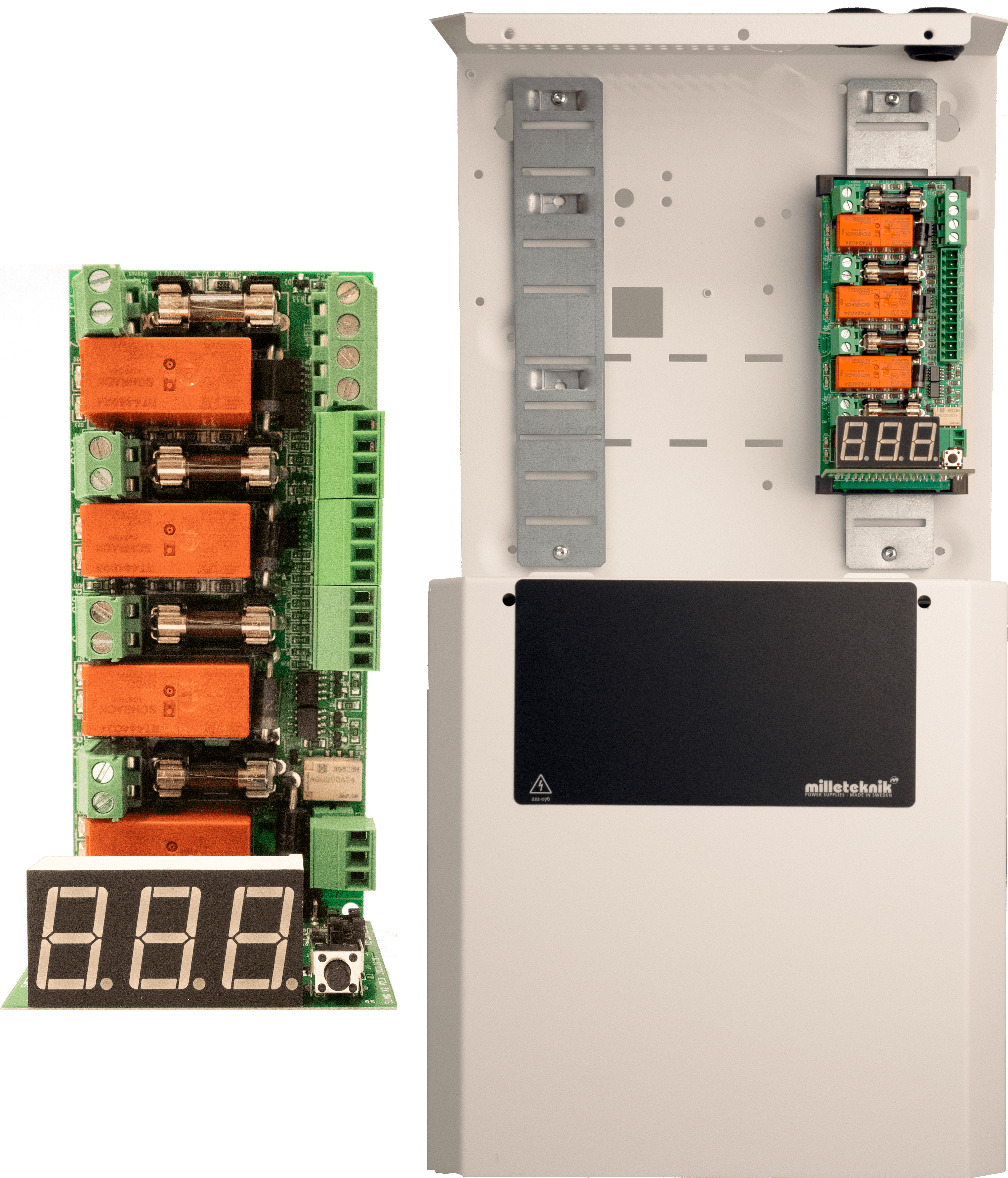
Four module 4 outputs in S
Fire module 4 outputs are delivered mounted in S-enclosure, ready for installation.
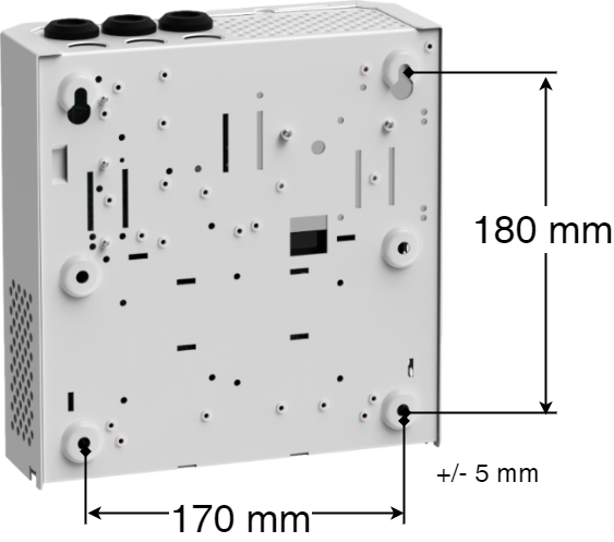
Wall mounting
Use four screws suitable for the wall to mount the cabinet.
The distance between the screw head and the wall should be 1.5–2 mm.
Preferably leave a 100 mm air gap around the unit.
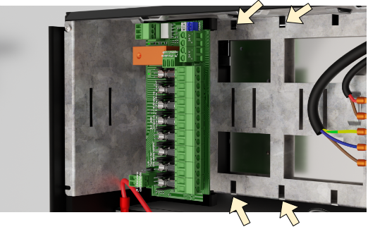
Installation of optional cards in FLX M or FLX L
Notice
The card in the picture is in the larger form factor. There are more cards in this form factor, but they are mounted in the same way. This means that the card in the picture may be different from the card you are mounting.
Start by folding down the plate in the battery backup in which the card should sit, see picture.
Fasten the card with the supplied screw, missing screw use sheet metal screw (2.9 x 6.5), before making connections, (to avoid short circuit).
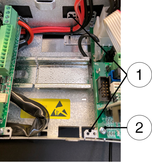
Fold down the "ears" and screw on the card.
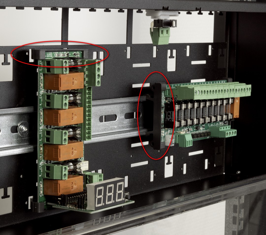
Installation of optional card in 19 rack module holder
Snap the card to any position (1-4, a-c, depending on the card's form factor / size).
 |
Positions for cards in 19 rack module holder
Number of places for circuit boards with a larger form factor: 4 pieces - marked 1-4 in the picture.
Number of places for circuit boards in the smaller form factor (L-module): 12 pcs - marked a-c in the picture. However, 8 (horizontal) optional cards have the most space (a, c), as the grooves in the middle (b) are adapted for standing cards.
Note
It is the installer's responsibility to consider wiring and cable lengths when installing circuit boards.
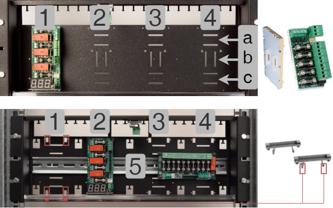
To the right is a card in the smaller form factor, for place a-c.
At the bottom right are plastic ends short of the larger form factor. These can be in place 1-4 or (5) DIN rail.
Connection
The following pages describe the card, how it is connected, other connections and configurations.
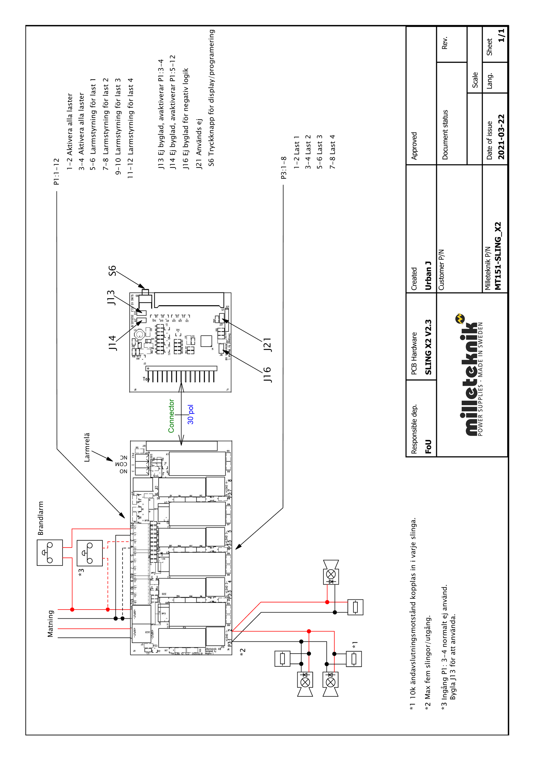
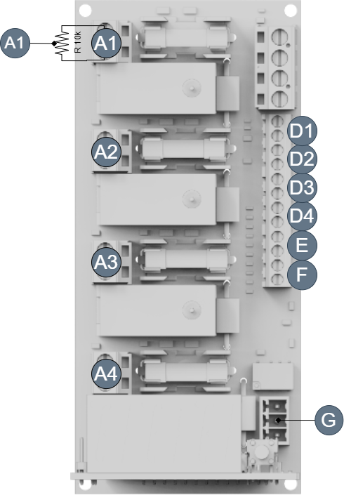
Description Fire module 4 outputs

On picture | On circuit boards | Explanation |
|---|---|---|
A 1-4 1-4 | R10K resistor Plus: P3: 2, 4, 6, 8 (in case of alarm) Minus: P3: 1,3, 5, 7 (in case of alarm) | Connection of alarm device on loop. On each output there is a 10K ohm resistor mounted, this resistor, remove this when switching on the alarm, see Example sketch of connecting loops Plus output on the card is polarity in case of alarm, (opposite in detection mode). |
B | F2, F3, F4, F6 | Load fuses |
C | P2: 1-4 | Input 24 V (double input). P2: 1, P2: 3 = + (plus). P2: 3, P2: 4 = - (minus). |
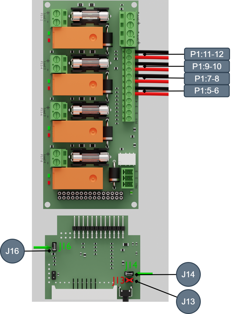
D 1-4 | P1: 5-12 | Connection of alarm device on A1-4, see Connection of load on Fire module 4 outputs P1:6, 8, 10, 12= - (minus). P1:5, 7, 9, 11= + (plus). |
E | P1: 3-4 | Activate all alarm device outputs on A 1-4, if D is jumpered from C. Input P1:3-4 is not activated (factory setting). The input is activated by jumpering J13 (7). P1:3= + (plus). P1:4= - (minus). |
F | P1: 1-2 | Activate all alarm device outputs on A 1-4. 24 V input from the alarm center activates all outputs. P1:1= + (plus). P1:2= - (minus). |
G | P4: 1-3 | Alarm output P4: 1 = NO P4: 2 = CO P4: 3 = NC |
H | S6 | Push button |
I | J3 | Display |
In picture | On circuit board | Explanation |
|---|---|---|
1 | J21 | When jumpered, output 1 and output 2 will not show calibration or impedance errors. |
2 | J16 | Not jumpered: Negative logic, (factory setting). Built: Positive logic. |
3 | D13, D16, D19, D23 | Illuminates with a solid green light when all loops are ok. Flashes green when alarm is controlled via (alarm control) input P1: 1-12. |
4 | D15, D17, D18, D20 | Glows with a solid red glow in the event of a loop error. Flashes red if a fuse is broken when the alarm is controlled via (alarm control) input P1: 1-12. |
5 | D12 | Illuminates with a solid green light when everything is ok, if it is off the alarm relay is activated. |
6 | J14 | Not bridged: Disable input 1-4 (factory setting). Jumper: Activate input 1-4. |
7 | J13 | "Fireman control" Used to activate input P1:3-4 (E). Delivered unbridged = not activated input, (jumper activates this input). |
Connection of Fire module 4 outputs to battery backup
Fire module 4 outputs must be connected to the motherboard (on the sum alarm output) in the battery backup.
Main board, PRO1 | - | Fire module 4 outputs |
Alarm: J15 | Connects to | Alarm output CO / NC |
Load: Load output 1 | Connects to | IN 12 V / 24 V |
Main board: PRO2 or PRO2 V3 | Fire module 4 outputs | |
Alarm: J7 | Connects to | Alarm output CO / NC |
Load: Load output 1 | Connects to | IN 24 V |
Main board: PRO3 | Fire module 4 outputs | |
Alarm: J10 | Connects to | Alarm output CO / NC |
Load: Load output 1 | Connects to | IN 12 V / 24 V |
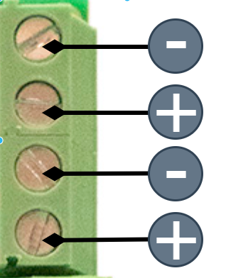
Connection of power supply from battery backup to optional card
Connect incomming voltaget to any input .
The card must be powered by 24 V DC.
The card has double inputs for easy bridging if battery backup has more optional cards fitted.
P2:1,3 | + |
P2:2,4 | - |
 | |
Connection of load on Fire module 4 outputs
Connection of load on Fire module 4 outputs is done on Group 1-4, see Description Fire module 4 outputs
Caution
Maximum load is 2 A per load output (F2A is fitted from the factory) and the card's total load must not exceed 8 A.
Connect load cabling to Load Path 1 - 4.
Connection of alarm device on loop. A 10K ohm resistor is mounted on each output. Remove this when connecting the alarm system, see Example sketch of connecting loops. 10K ohm resistors must be placed on each subloop end to ensure monitoring of the subloop. Several partial loops can be set see, Example sketch of connecting loops.
Connection of control voltage to the alarm device is connected to D, E and F (D1-4). E is disabled by default.
Alarm output for alarms from loop is connected to G.
Only then can battery backup be commissioned. See manual for battery backup.
Load | Controls | Explanation |
|---|---|---|
A1 | D4 | D4 controls A1 |
A2 | D3 | D3 controls A2 |
A3 | D2 | D2 controls A3 |
A4 | D1 | D1 controls A4 |
Alarm priority
If several sources are alarming, the priority is this:
Fire.
Activate all.
Individual input.
Negative and positive logic - overview of examples of connection
Alarm settings: negative and positive logic
Note
The card is set to negative logic from the factory.
The card must be jumpered on J16 for positive logic.
Negative logic = Alarm when control voltage disappears, (0 V). (J16 not jumpered, factory setting)
Positive logic = Alarm when the card is energized with 24 V on the alarm inputs. (J16 byglad)
Tip
See last page for electrical diagram.
Example one - Negative logic - common control (factory setting).
Example two: Negative logic - individual control.
Example three - Positive logic - shared control.
Example four: Positive logic - individual control.
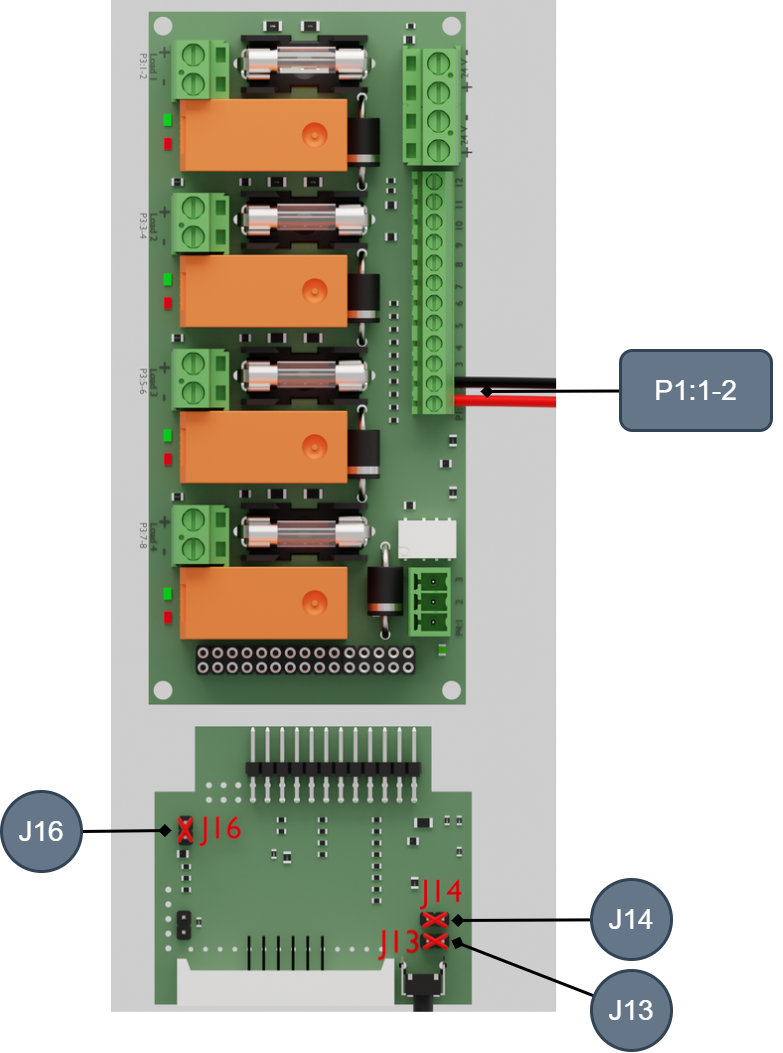
Example of connection 1 - Negative logic common control, factory setting.
On circuit board | Explanation |
|---|---|
J16 | Not bridged |
J14 | Not bridged |
J13 | Not bridged |
On circuit board | Explanation | 24 V DC | 0 V DC |
|---|---|---|---|
P1:1-2 | +/ | Normal / monitoring mode | Fire alarm mode (activated outputs) |
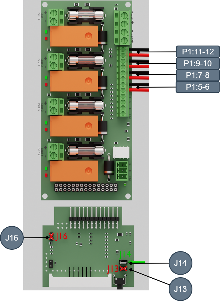
Example of connection 2 - Negative logic individual control
On circuit board | Explanation |
|---|---|
J16 | Not bridged |
J14 | Bridged |
J13 | Not bridged |
On circuit board | Explanation | 24 V DC | 0 V DC |
|---|---|---|---|
P1:5-6 | +/- | Normal / monitoring mode | Fire alarm mode (activated output 1) |
P1:7-8 | +/- | Normal / monitoring mode | Fire alarm mode (activated output 2) |
P1:9-10 | +/- | Normal / monitoring mode | Fire alarm mode (activated output 3) |
P1:11-12 | +/- | Normal / monitoring mode | Fire alarm mode (activated output 4) |
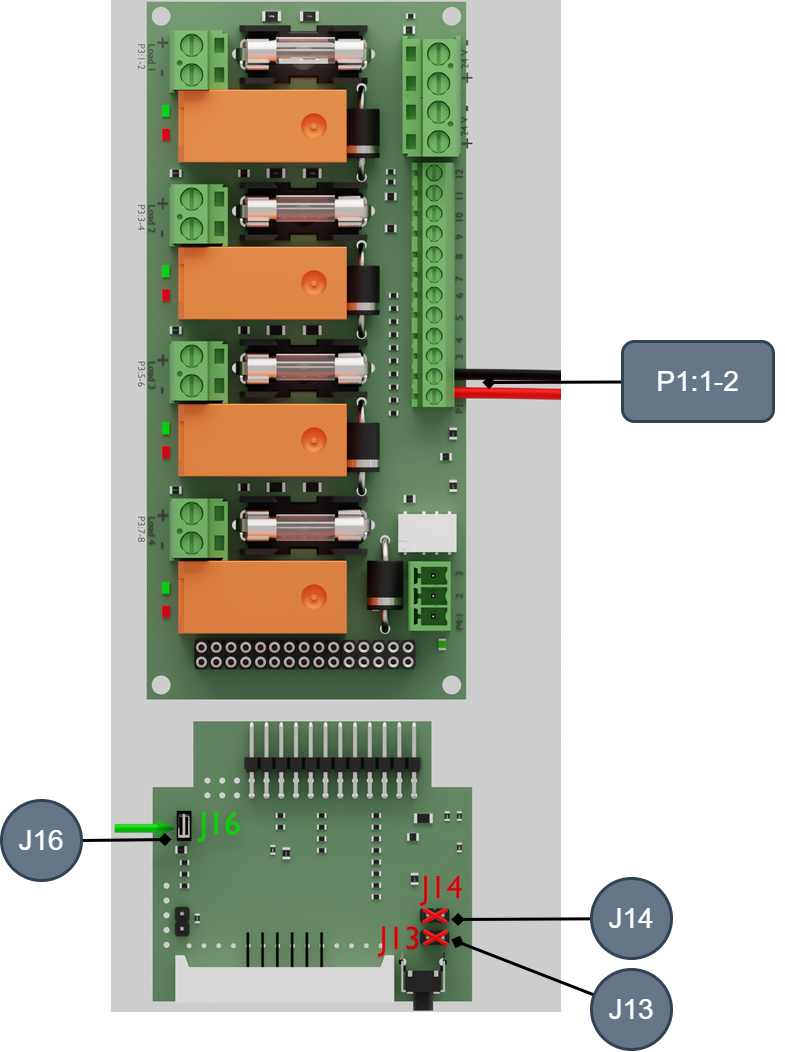
Example of connection 3 - Positive logic - common control
On circuit board | Explanation |
|---|---|
J16 | Bridged |
J14 | Not bridged |
J13 | Not bridged |
On circuit board | Explanation | 24 V DC | 0 V DC |
|---|---|---|---|
P1:1-2 | +/ | Fire alarm mode (activated outputs) | Normal / monitoring mode |
Example of connection 4 - Positive logic individual control
On circuit board | Explanation |
|---|---|
J16 | Bridged |
J14 | Bridged |
J13 | Not bridged |
On circuit board | Explanation | 24 V DC | 0 V DC |
|---|---|---|---|
P1:5-6 | +/- | Fire alarm mode (activated output 1) | Normal / monitoring mode |
P1:7-8 | +/- | Fire alarm mode (activated output 2) | Normal / monitoring mode |
P1:9-10 | +/- | Fire alarm mode (activated output 3) | Normal / monitoring mode |
P1:11-12 | +/- | Fire alarm mode (activated output 4) | Normal / monitoring mode |
Alarm settings: negative and positive logic
Note
The card is set to negative logic from the factory.
The card must be jumpered on J16 for positive logic.
Negative logic = Alarm when control voltage disappears, (0 V). (J16 not jumpered, factory setting)
Positive logic = Alarm when the card is energized with 24 V on the alarm inputs. (J16 byglad)
Tip
See last page for electrical diagram.
Connection of alarm settings in case of negative logic
Joint control only. Control on P1:1-2. J16, J14 and J13 must be unbridged.
Disable input 3-4*
Remove jumper at 7 (J13) to enable input 3-4.
*Fireman control
Connection of alarm settings with positive logic
Common control: Jumper 2 on J16. Control via P1:3-4.
Individual control: J16 and J14 bridged. Controls via P1:5-6, 7-8, 9-10 and 11-12.
Constant or pulsating alarm
Type of alarm is selected when programming cards. See:Alarm type programming after alarm output
Connection of fireman control
On E and F (P1:1-4) fireman control is connected.
Negative logic: 24 V on both inputs in normal operation, 0 V activates the alarm device output.
Positive logic: 0 V on both inputs in normal operation, 24 V activates alarm device output.
Input P1:3-4 is not activated (factory setting). The input is activated by jumpering J13 (7).
Connection to outputs for alarm devices
Each output can have up to five monitored alarm loops / alarms.
Each output gives an alarm, but it is not possible to see which of the 1-5 loops (which are connected to the output) is faulty.
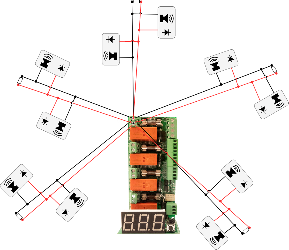
Example sketch of connecting loops
Each output can have up to five monitored loops. For each loop, a resistor is required to be mounted at the end of the loop. In the event of an interruption or short circuit, the load output indicator LED and alarm indicate the alarm output.
20 10k ohm resistors are included for connection at the end of each loop to be monitored.
Caution
Each individual loop does NOT receive a unique alarm.
Each individual alarm device does NOT receive a unique alarm.
Alarms are indicated per output and sum alarms are given.
Each alarm device must be equipped with or have a built-in rectifier diode.
10k ohm resistor should be connected at the end of each loop.
 |
Calibration and programming
To be able to calibrate the card, all loops must be correctly connected to the load outputs. When the card is started for the first time, it is not calibrated, a dot orange flashes at the bottom right of the display.
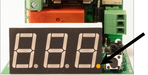 |
To calibrate:
Check that the dot at the bottom right of the display flashes orange.
Press the button next to the display and hold it down for 5 seconds until cAL appears on the display.
Release the button. The card now makes measurements on all connected loops and saves values.
When the dot at the bottom right of the display flashes green, the configuration is complete.
Note
Recalibration? Hold down the button for 5 seconds until the dot flashes orange, then perform steps 1-4.
Alarm type programming after alarm output
It is possible to choose fixed alarm or pulsating alarm. If no selection is made, the alarm type is fixed.
Select alarm type:
Select load output by pressing and holding the button for 5 seconds on the selected load output.
The display will now alternate between flashing for fixed alarm output or P for pulsing alarm output (0.8 seconds /0.8 seconds).
Press the button to confirm the programming. (Select the display when it is flashing or select p for pulsating alarms.)
Do you want to change? Go through steps 1-3 again to change the selection.
What is shown on the card display?
The display shows different status of connection to Fire module 4 outputs. Press the button to view various status and information. Display shows information in green, warnings in yellow and alarms in red.
Normal operation: All numbers are off and a flashing green dot appears in the lower right corner.
Push button: Pressing the button displays information.
Matrix for display
Green text | First sign | Second sign | Third sign |
Load output | C (Channel) | 1-4 | 1-5 |
Example of display is shown: C25=Load output 2 has 5 loops connected. | |||
Yellow text: ALL all load outputs activated via fire control or Activate all devices.
Yellow text | First sign | Second sign | Third sign |
Information | A (Enabled) | 1-4 | Off / not displayed |
Example of display is shown: A2=Load output 2 activated via alarm control. | |||
Red text | First sign | Second sign | Third sign | Explanation, third sign |
Warnings | E (Error)* | 1-4 | 0 | Interruption |
- | - | - | - | Short circuit |
- | - | - | A | Impedance error |
- | - | - | 1-5 | Number of whole loops |
An example of the display is shown: E 2 0= interruption on load aisle 2. Example of display only the third character is shown: 4 = 4 complete loops. When the third character is blank, it means the channel is shorted. Off = The channel is not used. 0 = Interruption - = short circuit A = Impedance error, may indicate the wrong resistance value or the wrong polarity when connecting the alarm device to the respective loop. Number = Calibration error, shows the number of measured resistances. After activated fire alarm for more than 10 seconds, display will count down 300 seconds (five minutes). This is to avoid that heated diodes can leak. Alarms will not be activated during this time, however fire alarms can activate these outputs. | ||||
Important
Prerequisites are that the connected fire alarm device has a rectifier diode installed. Leakage must be less than 20 µA.
Acknowledgment of alarms shown on the display
Important
Alarms appear on the display until they are acknowledged.
Alarms are acknowledged by a short press on the button.
Note
Only the display of alarms needs to be acknowledged. Alarm relay is not locked and returns as soon as the fault has disappeared, (without acknowledgment).
Maintenance - PCB
The circuit board must be installed in an indoor environment, class 1. The circuit board requires no maintenance.
CE marking
Each product has a CE label with information about the product and contact information for the manufacturer. If you are missing something or need more information, you should firstly turn to retailers who will also be able to answer questions about warranty and support. You can always contact the manufacturer if you have questions about the product's performance.
 |
Warranty
The product has a two-year warranty, from the date of purchase (unless otherwise agreed). Support during the warranty period can be reached at support@milleteknik.se or telephone, +46 31-34 00 230. Compensation for travel and / or working hours in connection with locating faults, installing repaired or replaced goods is not included in the warranty. Contact Milleteknik for more information. Milleteknik provides support during the product's lifetime, however, no later than 10 years after the date of purchase. Switching to an equivalent product may occur if Milleteknik deems that repair is not possible. Support costs may (at Milleteknik's discretion) occour after the warranty period has expired.
Technical data: Fire module 4 outputs
Info | Explanation |
|---|---|
Article title | Fire module 4 outputs |
E-number | 5257467 |
Article number | A-FU002404FS01 |
Product description | The Fire module 4 outputs alarm monitoring module has four individually controllable outputs with the possibility of a star network and up to five loops on each output. Alarm functions for both positive and negative logic. Alarm for fuse failure/loop failure. Fire man control and the possibility of individually pulsed outputs. Display for easy reading and configuration. The card replaces previous SlingX cards (52 696 18). |
Measure | 120 x 55 mm x 52 mm |
Entrances | Two entrances. (For alternative power supply when changing power supply. In order not to break the load voltage.) A terminal can be used as a superstructure for the next optional card, (only if the battery backup has room for two cards). |
Clamping | 24 V DC |
Power consumption (at rest) | 100 mA. |
Power consumption (in case of alarm) | 200 mA in case of alarm on all channels. |
Leakage current | The card assumes that devices connected to it do not have leakage current. If there is a leakage current in units connected to the product, it may behave outside the specification. Warranty does not apply if leakage current is connected to the product. |
Tension | 24 V DC |
Outputs | Four |
Insurance | Load output: plus (+) fused with F2A. |
Max load | Max load is 2A per load output. The card's total load must not exceed 8 A. |
Alarm outputs | Alarm outputs: Sum alarm in the event of a fuse fault and a broken loop, see indication below. Alarm on potential-free relay contact. |
Alarm via | Triggered load fuse and loop interruption via potential-free switching. |
Indication | Display showing operating status, alarms and errors. Operation indication: one indication diode per load output +/-. Steady green light = normal operation. |
The product fits in: | Own enclosure with separate 24V power supply. And in 24 V battery backup *. |
* The product is not co-certified with NOVA and may not be used if a certificate is to be maintained. | |
Debug loop connected to the card
In idle mode, the board sends out a constant current on each loop that is about 408µA, this current can be verified by setting a multimeter to current measurement in series with the loop.
Number of resistors (10kΩ) | Type voltage on the loop | Allowable tolerance | Maximum rated voltage | Lowest rated voltage |
|---|---|---|---|---|
Break if voltage is more than 4.5 V. Short circuit if voltage is less than 0.35 V. "A" is displayed for voltage values outside the above ranges. May be due to impedance failure in the loop. Check individual dons in the loop have correct polarity and 10K ohm resistor connected. | ||||
1 | 4.08V | ± 0.25V | 4.33V | 3.83V |
2 | 2.04V | ± 0.2V | 2.24V | 1.84V |
3 | 1.36V | ± 0.15V | 1.51V | 1.2 1V |
4 | 1.02V | ± 0.1V | 1.12V | 0.92V |
5 | 0.816V | ± 0.1V | 0.916V | 0.716V |
Note
In connection with calibration, the loop's precisely measured voltage is saved, and it is based on this that the permitted maximum and minimum voltage is calculated from the permitted tolerance in the table above. It is therefore not the type voltage that is used. However, the voltage measured during calibration must be within the voltage range shown in the table below.
If the voltage of the loop in rest mode is above 4.5 Volts, a break is assumed. Display shows red; <channel> " ".
If the voltage of the loop in rest mode is below 0.35 Volts, a short circuit is assumed. Display shows red; <channel> 0.
If the voltage of the loop is between the permitted measurement ranges, Troubleshoot the loop. Display shows red; E <channel> A.
If the loop measures a different number of resistances than calibrated. Display shows red; E <channel> <measured number>.
Test the loop
Disconnect at least one of the wires from the Sling board and measure the resistance of the loop.
If the resistance (eg 10kΩ) does not correspond to the expected voltage, in this case approx. 4.08V even though the current measurement shows 408uA, there is a fault in the loop. It can be caused by incompatible don/sound siren which must be connected with a diode in series so as not to affect the impedance of the loop when it is in rest mode.
About translation of this document
User manual and other documents are in the original language in Swedish. Other languages are machine translated and not reviewed, errors may occur.
Electrical diagram