Installation and commissioning
Mounting
The card can be mounted in battery backup from the factory, in its own enclosure or sent as a loose card.
Important
The card must calibrated before use.
Four module 4 outputs in S
Fire module 4 outputs are delivered mounted in S-enclosure, ready for installation.
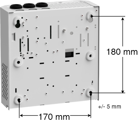
Wall mounting
Distance between screw head and wall should be 1.5–2 mm. Preferably leave a 100 mm air gap around the unit.
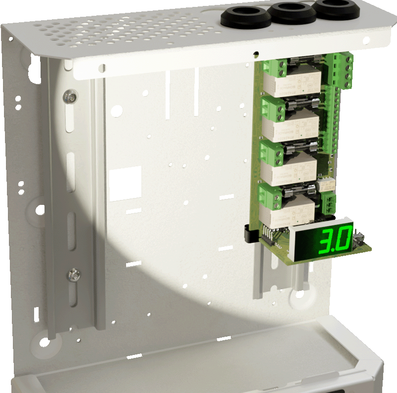
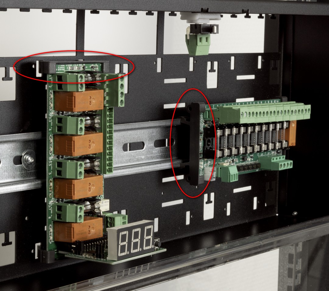
Installation of optional boards with plastic spacers in FLX M or FLX L
Notice
The card in the picture is in the larger form factor. There are more cards in this form factor, but they are mounted in the same way. This means that the card in the picture may be different from the card you are mounting.
Snap the card into the tray underneath.
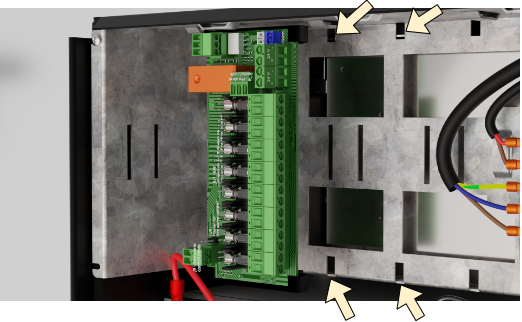
Mounting of optional boards on sheet metal in FLX M or FLX L
Notice
The card in the picture is in the larger form factor. There are more cards in this form factor, but they are mounted in the same way. This means that the card in the picture may be different from the card you are mounting.
Start by folding the plate into the battery backup where the card will be located, see picture.
Screw the board with the supplied screw, missing screw use plate screw (2.9 x 6.5), before making connections, (to avoid short circuit).
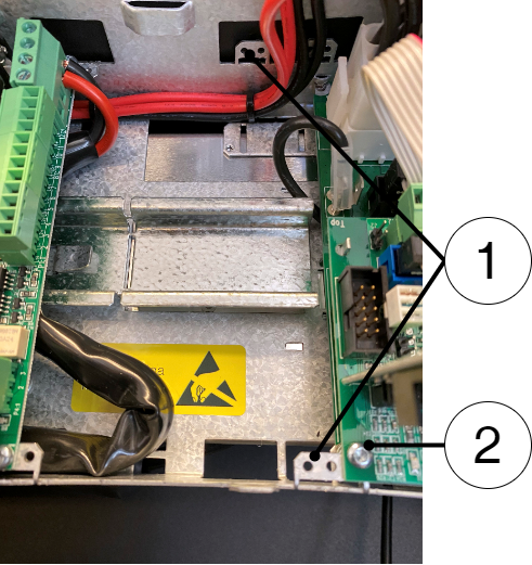
Fold down the “ears” and screw the board.
Installation of optional card in 19 rack module holder
Snap the card to any position (1-4, a-c, depending on the card's form factor / size).
 |
Positions for cards in 19 rack module holder
Number of slots for circuit boards with a larger form factor: 4 pieces - marked 1-4 in the picture.
Number of places for circuit boards in the smaller form factor (L-module): 12 pcs - marked a-c in the picture. However, 8 (horizontal) optional cards have the most space (a, c), as the grooves in the middle (b) are adapted for standing cards.
Note
It is the responsibility of the installer to consider wiring and cable lengths when installing circuit boards.
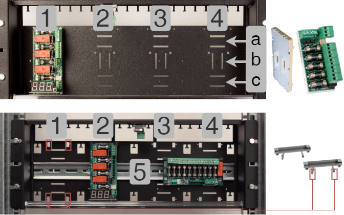
To the right is a card in the smaller form factor, for place a-c.
At the bottom right are plastic ends short of the larger form factor. These can be in place 1-4 or (5) DIN rail.
Connection
The following pages describe the card, how it is connected, other connections and configurations.
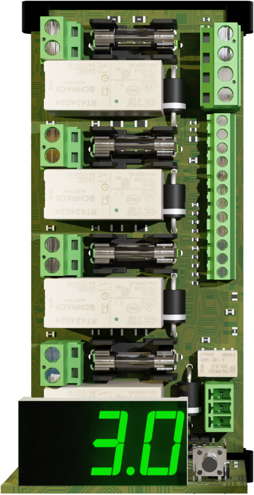
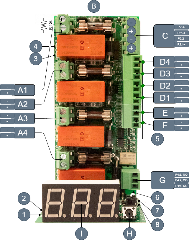
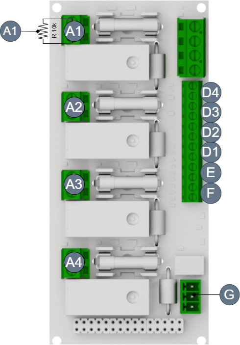
Description Fire module 4 outputs
On picture | On circuit boards | Explanation |
|---|---|---|
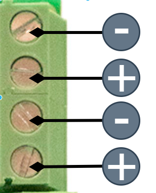
And 1-4 | (R10 k Ω resistor) Plus: P3: 2, 4, 6, 8 (in case of alarm) Minus: P3: 1,3, 5, 7 (in case of alarm) | Connecting the alarm device on loop. On each output, a 10 k Ω resistor is mounted. Remove this when switching on the alarm device Example of plugging in loops Plus output on the board is polarity in case of alarm, (on the contrary, in sensing mode). |
B | F2, F3, F4, F6 | Load fuses |
C | +INPUT- | Entrance 24V (double entry). Supply voltage + (plus against display). - (minus). |
D 1-4 | D 1-4 plus D 1-4 Minus | Switching control signal for individual control, see Example of connection 2 - Negative logic individual control, Example of connection 3 - Positive logic - joint control, Example of connection 4 - Positive logic individual control + (plus against display). - (minus). |
E | +E- | Activate all alarm device outputs on A 1-4. Input E is not enabled (factory reset). The input is activated by bridging J13. + (plus against display). - (minus). |
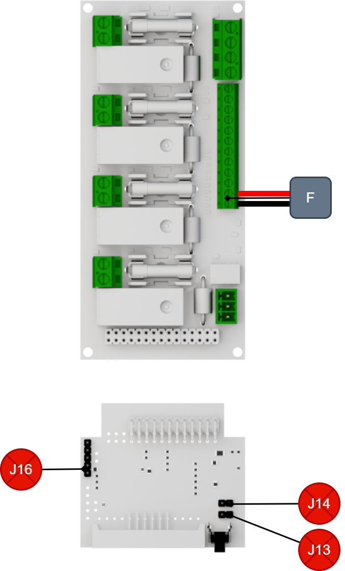
F | +F- | Activate all alarm outputs on A 1-4. 24 V input from the alarm center activates all outputs. + (plus against display). - (minus). |
G | P4:1-3 | Alarm output in case of loop failure. P4:1 = NC P4:2 = CO P4:3 = NO |
H | S6 | Push Button |
I | U1 | Display |
In picture | On circuit board | Explanation |
|---|---|---|
1 | J21 | In the case of the jumper, output 1 and output 2 will not alarm for loop failure. |
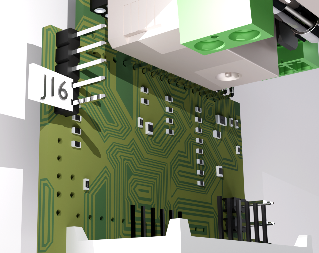
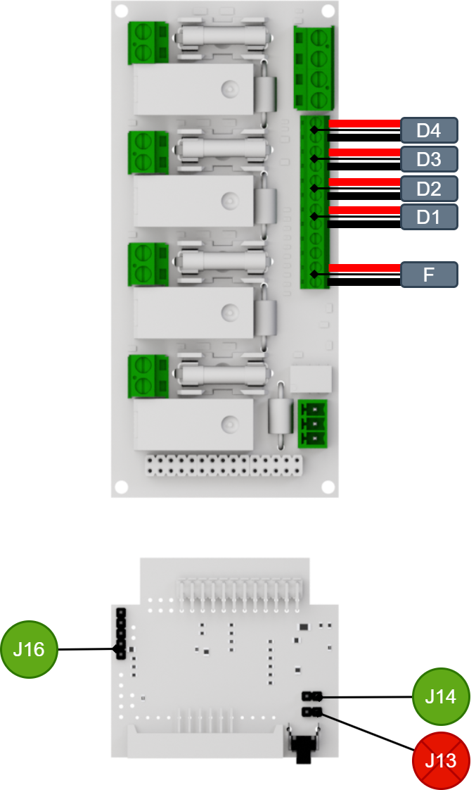
2 | J16 | Not jumperted: Negative logic, (factory reset). Jumpered: Positive logic |
3 | D13, D16, D19, D23 | Glows with solid green light when all loops are ok. Flashes green when alarm is controlled via (alarm control) input D 4 - 1 |
4 | D15, D17, D18, D20 | Glows with solid red light in case of loop failure. Flashes red if a fuse is broken when alarm is controlled via (alarm control) input D 4 - 1, E and F. |
5 | D32-37 | Glows with solid green light if 24 V is connected to input D4-1, E, F. |
6 | D12 | Glows with solid green light when loops are ok, it is off, alarm relay is activated. |
7 | J14 | Not jumpered: Disable input D 1-4 (factory reset). Jumpered: Enable input D 1-4 |
8 | J13 | "Fireman control" Used to activate input P1:3-4 (E). Delivered unbridged = not activated input, (jumper activates this input). |
Connecting Fire module 4 outputs to battery backup
Fire module 4 outputs must be connected to the motherboard (on the sum alarm output) in the battery backup.
Main Board, PRO1 | - | Fire module 4 outputs |
Alarm: J15 | Connects to | Alarm output CO/NC |
Load: Load output 1 | Connects to | IN 24V |
Main board: PRO2 or PRO2 V3 | Fire module 4 outputs | |
Alarm: J7 | Connects to | Alarm output CO/NC |
Load: Load output 1 | Connects to | IN 24 V |
Main board: PRO3 | Fire module 4 outputs | |
Alarm: J10 | Connects to | Alarm output CO/NC |
Load: Load output 1 | Connects to | IN 24V |
24 V connection from battery backup to optional card
The input voltage on optional boards is connected at any input input for supply voltage (INPUT).
The board must be powered by 24 V DC.
The card has dual inputs for smooth bridging if the battery backup has more optional cards fitted.
P2:1,3 | +/- Plus vs display. |
 | |
Plugging in load on Fire module 4 outputs
The connection of the alarm device on Fire module 4 outputs is done on A1-A4, see Description Fire module 4 outputs
Caution
Maximum load is 2 A per load output (F2A is fitted from the factory) and the card's total load must not exceed 8 A.
Connect load cable to A.
Connection of alarm device on loop. A 10K ohm resistor is mounted on each output. Remove this when connecting the alarm system, see Example of plugging in loops. 10K ohm resistors must be placed on each subloop end to ensure monitoring of the subloop. Several partial loops can be set see, Example of plugging in loops.
Connection of control voltage to the alarm device is connected to D, E and F (D1-4). E is disabled by default.
Alarm output for alarms from loop is connected to G.
Only then should the battery backup be deployed. See manual for battery backup
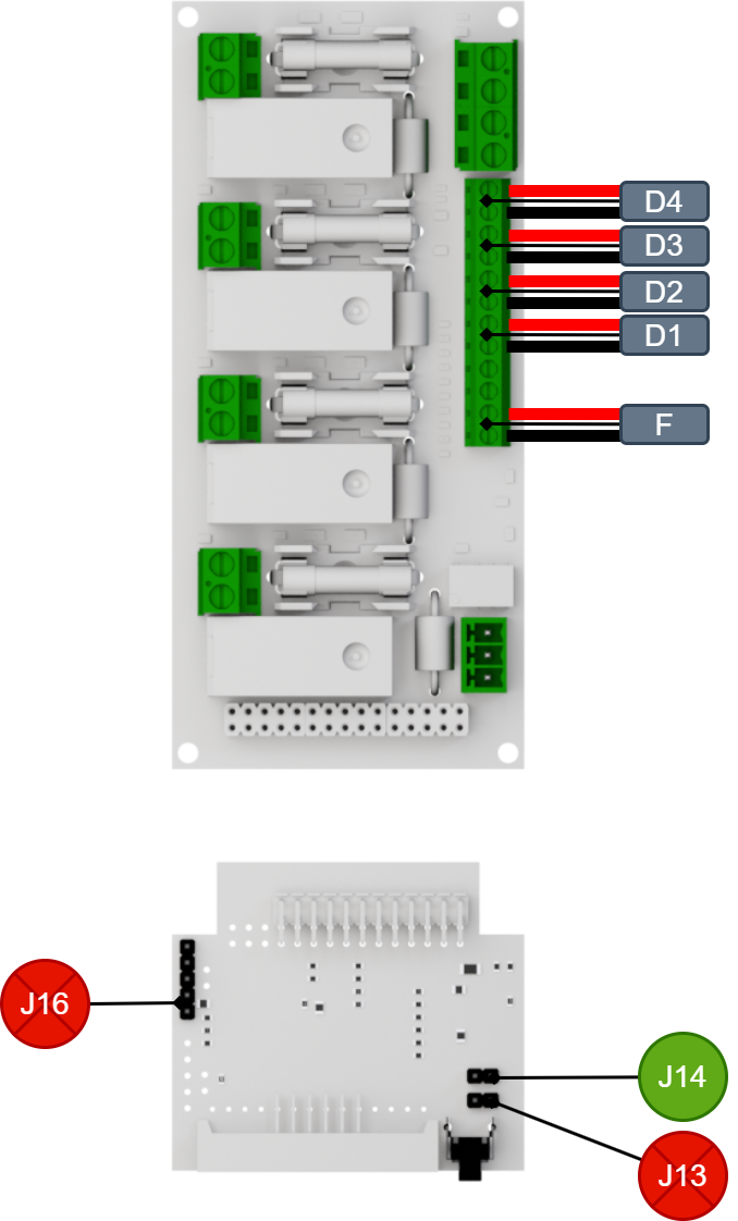
Explanation |
|---|
D4 controls A1 |
D3 controls A2 |
D2 controls A3 |
D1 controls A4 |
F controls A1-A4 (although E is active). |
Alarm priority
If several sources are alarming, the priority is this:
Fire. On display AL.L
Activate all. On display A.LL
Individual entrance. On display A1, A2, A3 or A4.
Negative and positive logic - overview of examples of connection
Alarm settings: negative and positive logic
Note
The card is set to negative logic from factory and the J16 is not jumpered.
The card should be jumpered on J16 for positive logic.
Negative logic = Activates alarm outputs when control voltage is broken, (0 V). J16 not jumpered, factory setting
Positive logic = Activates alarm device outputs when control voltage gives 24 V. J16 jumpered. The alarm inputs (D1-4, E, F), are not powered from the board. 24 V to the alarm inputs can be supplied by external 24 V or from the 24 V terminal +INPUT- .
The J16 is not jumpered from the factory.
Important
Green = closed jumper.
Example of connection 1 - Negative logic common control, factory setting.
On circuit board | Explanation |
|---|---|
J16 | Not jumpered, negative logic. |
J14 | Not jumpered, common steering. |
J13 | Not jumpered, Input E is not used. |
Denomination | Explanation | 24V DC | 0 V DC |
|---|---|---|---|
F | +/- | Normal/monitoring mode. | Fire alarm mode (activated outputs, A1 - A4). |
Example of connection 2 - Negative logic individual control
On circuit boards | Explanation |
|---|---|
J16 | Not jumpered, negative logic. |
J14 | Jumpered, individual control. |
J13 | Not jumpered, input E is not used. |
Important
Green = closed jumper.
Denomination | Explanation | 24V DC | 0 V DC |
|---|---|---|---|
D1 | +/- | Normal/monitoring mode | Fire alarm mode (activated output A1). |
D2 | +/- | Normal/monitoring mode | Fire alarm mode (activated output A2). |
D3 | +/- | Normal/monitoring mode | Fire alarm mode (activated output A3). |
D4 | +/- | Normal/monitoring mode | Fire alarm mode (activated output A4). |
F | +/- | Normal/monitoring mode | Fire alarm mode (activated outputs A1-A4). |
Example of connection 3 - Positive logic - joint control

On circuit boards | Explanation |
|---|---|
J16 | jumpered, positive logic. |
J14 | Not jumpered, common steering. |
J13 | Not jumpered, input E is not used. |
Important
Green = closed jumper.
Denomination | Explanation | 24V DC | 0 V DC |
|---|---|---|---|
F | +/- | Fire alarm mode (activated outputs). | Normal/monitoring mode. |
Example of connection 4 - Positive logic individual control
On circuit boards | Explanation |
|---|---|
J16 | Jumpered, positive logic. |
J14 | Jumpered, individual control. |
J13 | Not jumpered, not used. |
Important
Green = closed jumper.
Denomination | Explanation | 24V DC | 0 V DC |
|---|---|---|---|
D1 | +/- | Fire alarm mode, (activated output A1). | Normal/monitoring mode. |
D2 | +/- | Fire alarm mode, (activated output A2). | Normal/monitoring mode. |
D3 | +/- | Fire alarm mode, (activated output A3). | Normal/monitoring mode. |
D4 | +/- | Fire alarm mode, (activated output A4). | Normal/monitoring mode. |
F | +/- | Fire alarm mode (activated outputs). | Normal/monitoring mode. |
Alarm settings: negative and positive logic
Note
The card is set to negative logic from factory and the J16 is not jumpered.
The card should be jumpered on J16 for positive logic.
Negative logic = Activates alarm outputs when control voltage is broken, (0 V). J16 not jumpered, factory setting
Positive logic = Activates alarm device outputs when control voltage gives 24 V. J16 jumpered. The alarm inputs (D1-4, E, F), are not powered from the board. 24 V to the alarm inputs can be supplied by external 24 V or from the 24 V terminal +INPUT- .
The J16 is not jumpered from the factory.
Turning on alarm settings in case of negative logic
Joint control only. Control on P1:1-2. J16, J14 and J13 = not jumpered.
Individual control: J14 jumpered. Controls via D1, D2, D3 and D4 .
Disable input 3-4*
Remove jumper at 7 (J13) to enable input 3-4.
*Fireman control
Turning on alarm settings in case of positive logic
Joint control only: Jumper on J16. Steering via F. If J13 is jumpered also controls E.
Individual control: J14 and J16 jumpered, control via D1-D4.
Constant or pulsating alarm outputs
type of alarm is selected when programming cards. See:Programming alarm type after alarm output
Connection of fireman control
Notice
Fireman control can also be called sum control.
Input E is not enabled (factory reset). The input is activated by bridging J13.
On E and F (P1:1-4) fireman control is connected.
Negative logic: 24V on either inputs in normal operation, 0 V activates all alarm device outputs.
Positive logic: 0 V on either input in normal operation, 24V activates all alarm device outputs.
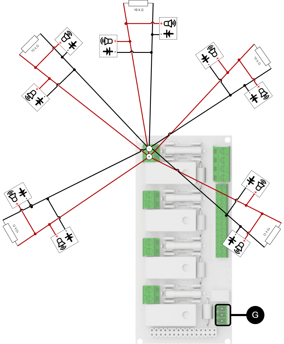
Switching on the alarm device
Each output can have up to five monitored (star mesh) alarm loops/alarm devices.
This means that each output can give a general alarm when something is wrong, but the system cannot specify exactly which of the up to five loops connected to the same output is causing the error. In other words, the alarm indicates a problem on the specific output, but does not identify which specific loop within that output has the error .
Example of plugging in loops
Each output (A1-A4) can have up to five monitored loops. To monitor each loop, a resistor is required to be mounted at the end of the loop. In case of interruption or short circuit, the load output indication diode, alarm on the alarm output, indicates (P 4:1-3) and is displayed on display .
20 pieces of 10k Ω resistors included. A resistor shall be fitted at the end of each loop.
Caution
Unique alarm is given only per output.
Each individual subloop on an output does NOT receive a unique alarm.
In the case of multiple alarm devices on loop, each individual alarm device does NOT receive a unique alarm.
Alarms are indicated per output and sum alarms are given.
Each alarm device must be equipped with or have a built-in rectifier diode.
10k Ω resistors shall be connected at the end of each subloop.
 |
Output | Loop | Alarm on loop | Alarm on output | Alarm appears on display? | Alarm on output |
|---|---|---|---|---|---|
1 | 1 | No | Yes | Yes (E1A, E1-E1O.) | G |
2 | Yes | ||||
3 | No | ||||
4 | No | ||||
5 | No |
Calibration and programming
Important
The card must be calibrated before use.
In order to calibrate the board, all loops must be properly connected to resistors. When the card is started for the first time, it is not calibrated, at the bottom right of the display a dot flashes orange
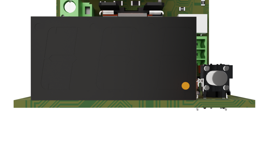
To calibrate the first time:
Make sure that the dot at the bottom right of the display flashes orange.
Press and hold the button next to the display until CAL appears on the display.
Release the button. The card now takes measurements on all connected loops and
When the point at the bottom right of the display flashes green, calibration is complete.
Note
Recalibration? Do steps 2-4.
If E1, E2, E3, or E4 are displayed during calibration, check that 10kΩ resistors are correctly connected.
The alarm device must have a rectifier diode.
Important
In the case of alarm control Axx it is not possible to start calibration. Turn off alarm control to calibrate.
Resetting settings
Make the card voltage free.
Hold the button.
Voltage mode board.
Press and hold the button until display shows: rSt.
At the bottom right, the dot flashes orange.
Recalibrate the card.
Programming alarm type after alarm output
It is possible to choose fixed alarm or pulsating alarm. If no selection is made, the alarm type is fixed.
Point at the bottom right of the display should flash green.
Press the button, but do not hold the button.
It says c1 on display and how many resistors are plugged into that channel. Example: If there are 2 resistors connected to channel 1, it says c12.
If you hold the button in this position for about 5 seconds, the last character starts blinking P. The pulsating alarm is now activated.
[sv]
Press the button briefly or wait for about five seconds and the mode will end automatically.
Repeat the procedure for each channel.
What is shown on the card display?
The display shows different status of connection to Fire module 4 outputs. Press the button to view different status and information. Display shows information in green, alerts in orange and alarms in red
Normal operation: All numbers are off and a flashing green dot appears in the lower right corner.
Push button: Pressing the button displays information.
Matrix for display
Green | ||
|---|---|---|
Letter | Load output/channel no | Number of loops |
c (Channel) | 1-4 | 1-5 |
Example display shown: C25=load output 2 has 5 loops connected. | ||
Orange (information) | ||
|---|---|---|
Letter | Load output/channel no | Third sign |
A (Enabled) | 1-4 | Off / not displayed |
Example display shown: A2=Load output 2 activated via alarm control. Yellow text: AL.L all load outputs activated via firefighter control or A.LL to activate all don. It says A.L.L. are both activated. | ||
Red (Alerts and Alarms) | |||||||||||||||||||||||||||||||||||||||||||||||||
|---|---|---|---|---|---|---|---|---|---|---|---|---|---|---|---|---|---|---|---|---|---|---|---|---|---|---|---|---|---|---|---|---|---|---|---|---|---|---|---|---|---|---|---|---|---|---|---|---|---|
Letter | Load output/channel no | Third sign | Explanation, third sign | ||||||||||||||||||||||||||||||||||||||||||||||
E (Erro) | 1-4 | O (Open) | Interruptions | ||||||||||||||||||||||||||||||||||||||||||||||
- | Short circuit | ||||||||||||||||||||||||||||||||||||||||||||||||
A (Attención) | Impedance error[a] | ||||||||||||||||||||||||||||||||||||||||||||||||
Calibration error | |||||||||||||||||||||||||||||||||||||||||||||||||
Example display is shown: E 2 0= interruption of load output 2. Example of display is shown, third character: 4 = 4 detected loops. Extinguished = error in calibration. After activated alarm for more than 60 seconds, display will count down 300 seconds (five minutes). This is to avoid that heated diodes can leak. Alarms will not be activated during this time, however fire alarms can activate these outputs. If the alarm is less than 60 seconds, the display will count down 20 seconds. The countdown appears within 10 seconds. During the countdown time, the device alarms for loop errors and/ or impedance errors. | |||||||||||||||||||||||||||||||||||||||||||||||||
[a] May indicate the wrong resistance value or the wrong polarity when switching the alarm device on the respective loop | |||||||||||||||||||||||||||||||||||||||||||||||||
Important
Prerequisites are that connected fire alarm devices have rectifier diode installed.
List of what the display can display
Color of text | On display | Explanation |
|---|---|---|
Red |  | Error Channel 1 - interrupt (0=Open/open). |
Red | 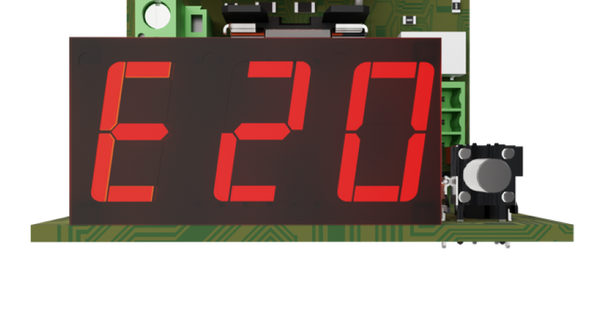 | Error Channel 2 - interrupt (0=Open/open). |
Red | 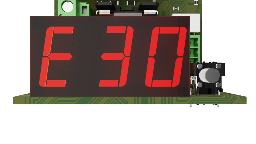 | Error Channel 3 - interrupt (0=Open/open). |
Red | 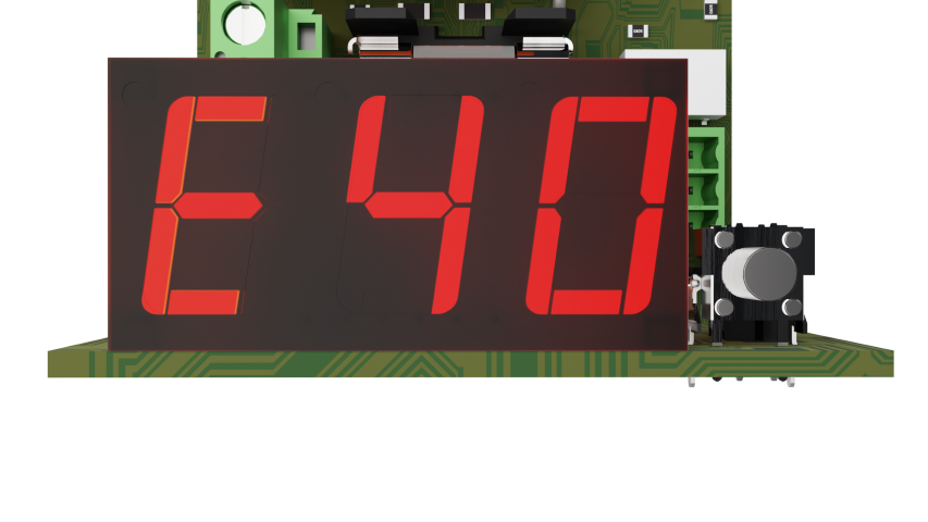 | Error Channel 4 - interrupt (0=Open/open). |
Red |  | Loop failure on fuse/triggered fuse on any output, (A1-A4). Also the text xx0 can mean triggered fuse. |
Red | 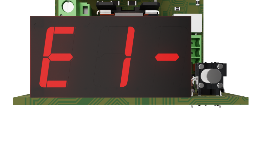 | Loop fault (Error) Channel 1 - short circuit |
Red |  | Loop error (Error) Channel 2 - short circuit. |
Red | 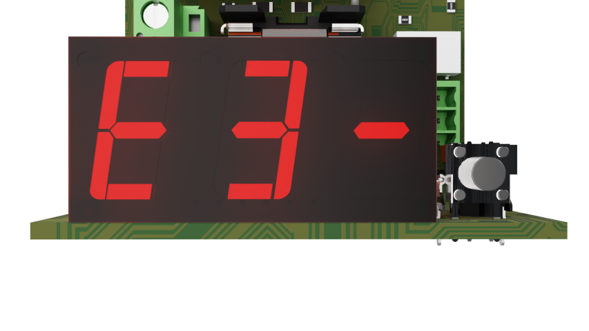 | Loop error (Error) Channel 3 - short circuit. |
Red | 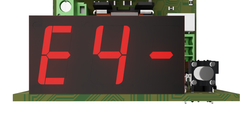 | Loop error (Error) Channel 4 - short circuit. |
Red | 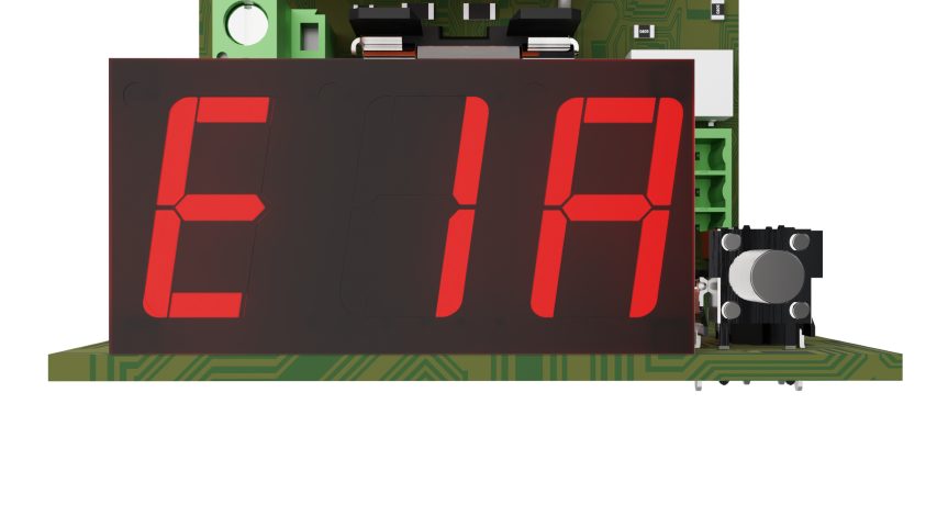 | Loop Error Channel 1 - Impedance error, (A=Attention). |
Red | 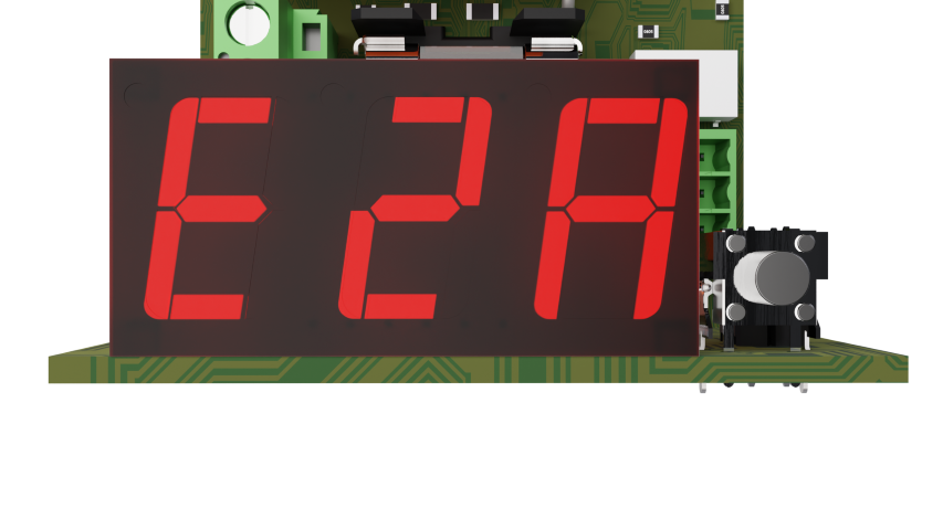 | Loop Error Channel 2 - Impedance error, (A=Attention). |
Red |  | Loop Error Channel 3 - Impedance error, (A=Attention). |
Red | 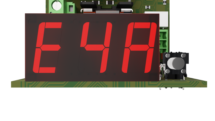 | Loop Error Channel 4 - Impedance error, (A=Attention). |
Green |  | Information Channel 1 (with 5 resistors/loops detected). |
Green | 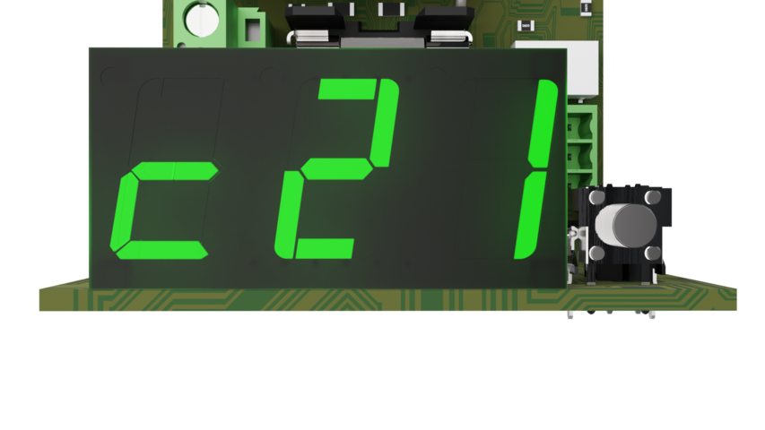 | Information Channel 2 (with 1 resistor/loop detected). |
Green | 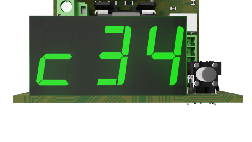 | Information Channel 3 (with 4 resistors/loops detected), |
Green | 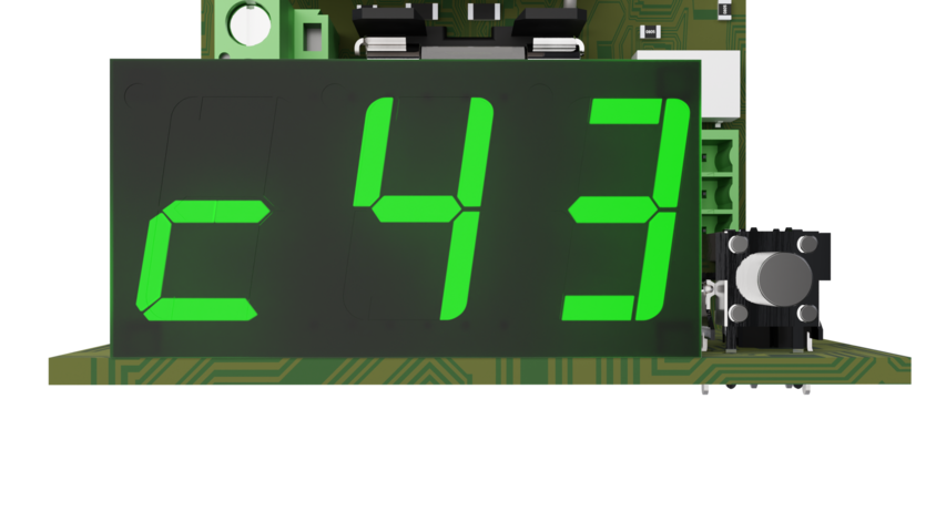 | Information Channel 4 (with 3 resistors/loops detected). |
Green |  | Pulsating alarm, |
Green |  Pulsating alarm, display switches. | |
Orange | 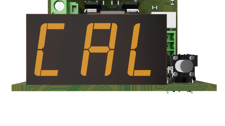 | Calibration. |
Orange/green | 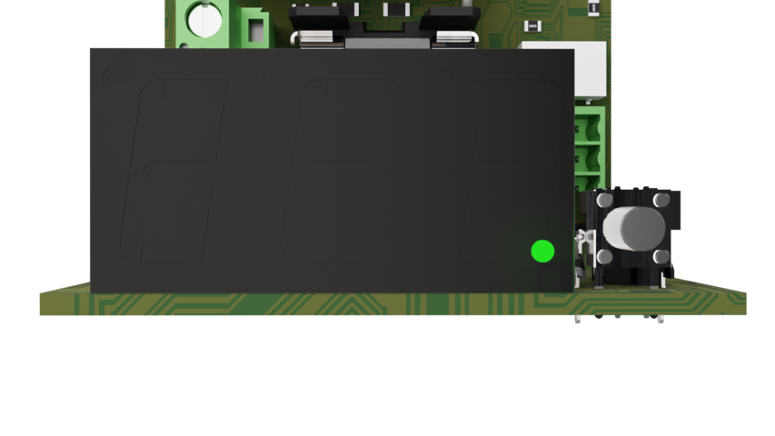 Flashes orange on uncalibrated system and flashes green on calibrated system. | |
Orange | 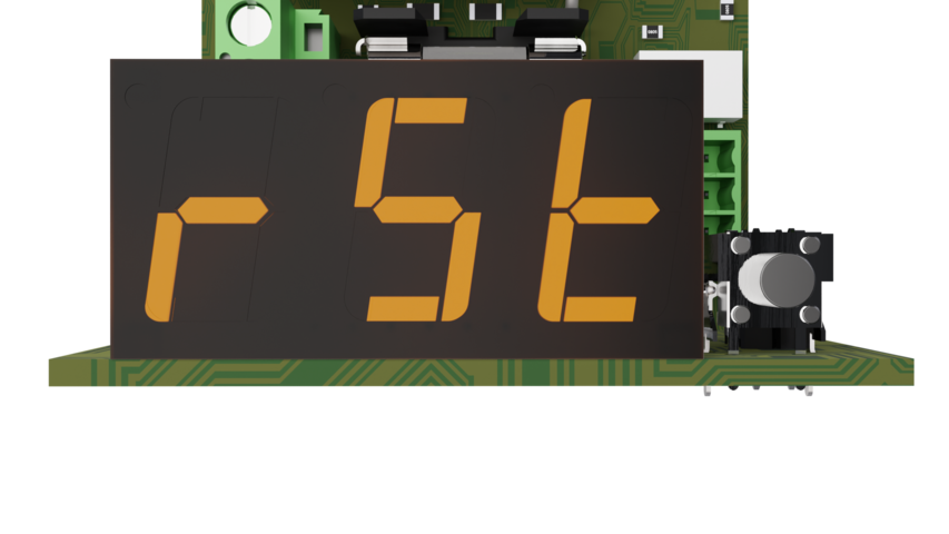 | Restore/reset |
Green | | Green blink, sleep mode. Calibrated system. No active alarms |
Red | 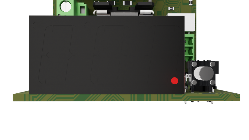 | Ongoing error acknowledgement. |
Orange |  | All load outputs activated via firefighter control. E-input |
Orange |  | All load outputs enabled. F input |
Orange | 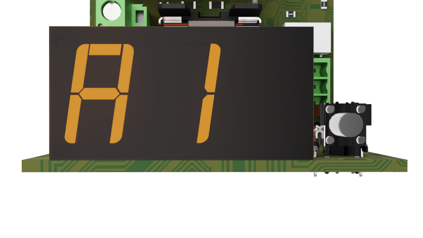 | Active alarm on load output A1. |
Orange |  | Active alarm on load output A2. |
Orange | 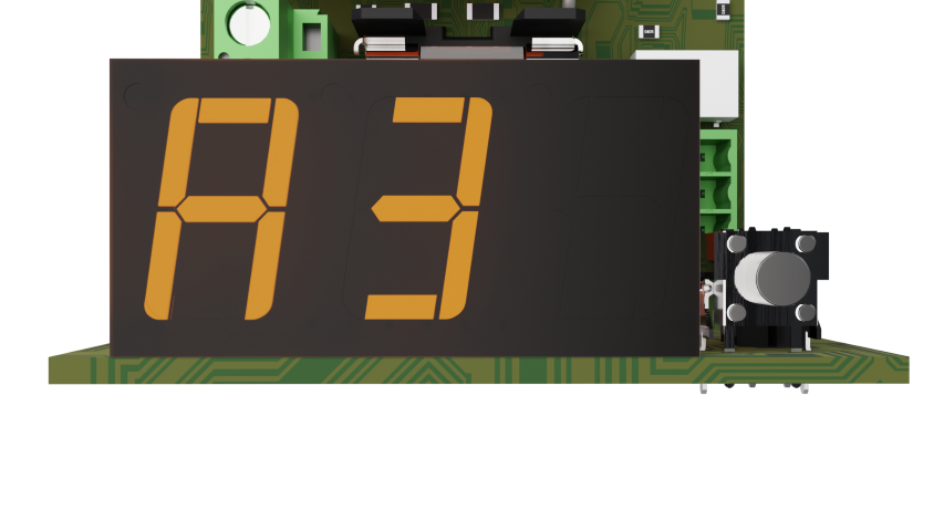 | Active alarm on load output A3. |
Orange |  | Active alarm on load output A4. |
Other display information | C18 or C28 | If the device is buggy to have channels 1 and 2 turned off for loop alarms, and the resistors on those channels are subsequently disconnected, “C1o” and “C2o” do not appear in the C menu as expected. Instead, “c18 appears. “and “c28, respectively. “with green text. This does not affect the functionality, but should be noted as an alternative mode of display in this mode |
Acknowledgment of alarms shown on the display
Important
Alerts for errors are displayed on display until they are acknowledged.
Alarm for failure can be set off by a short press of the button or by rebooting (on/off).
Note
Only the display of alarms needs to be acknowledged. Alarm relay is not locked and returns as soon as the fault has disappeared, (without acknowledgment).
Maintenance - PCB
The circuit board must be installed in an indoor environment, class 1. The circuit board requires no maintenance.
CE marking
Each product has a CE label with information about the product and contact information for the manufacturer. If you are missing something or need more information, you should firstly turn to retailers who will also be able to answer questions about warranty and support. You can always contact the manufacturer if you have questions about the product's performance.
 |
Warranty
The product has a two-year warranty, from the date of purchase (unless otherwise agreed). Support during the warranty period can be reached at support@milleteknik.se or telephone, +46 31-34 00 230. Compensation for travel and / or working hours in connection with locating faults, installing repaired or replaced goods is not included in the warranty. Contact Milleteknik for more information. Milleteknik provides support during the product's lifetime, however, no later than 10 years after the date of purchase. Switching to an equivalent product may occur if Milleteknik deems that repair is not possible. Support costs may (at Milleteknik's discretion) occour after the warranty period has expired.
Technical data: Fire module 4 outputs
Info | Explanation |
|---|---|
Article title | Fire module 4 outputs |
E-number | 5257467 |
Article number | A-FU002404FS01 |
Product description | The Fire module 4 outputs alarm monitoring module has four individually controllable outputs with the possibility of a star network and up to five loops on each output. Alarm functions for both positive and negative logic. Alarm for fuse failure/loop failure. Fire man control and the possibility of individually pulsed outputs. Display for easy reading and configuration. The card replaces previous SlingX cards (52 696 18). |
Measure | 120 mm. x 55 mm. x 52 mm. |
Inputs (24 V) | Two entrances. (For alternative power supply when changing power supply. In order not to break the load voltage.) A terminal can be used as a superstructure for the next optional card, (only if the battery backup has room for two cards). |
Clamping | 27.3 V DC. |
Power consumption (at rest) | 100 mA. |
Power consumption (in case of alarm) | 200 mA in case of alarm on all channels. |
Leakage current | The card assumes that connected devices do not have leakage current. If leakage current is present in devices connected to the product, it may behave beyond specification. Warranty does not apply if devices with leakage current are connected to the product . |
Tension | 27.3 V DC |
Outputs | Four |
Insurance | Load output: plus (+) fused with F2A. |
Max load | Max load is 2A per load output. The card's total load must not exceed 8 A. |
Alarm inputs | Six. |
Alarm outputs | Alarm outputs: Sum alarm in case of fuse failure and loop break. Alarm via potential-free relay connector. |
Alarm via | Triggered load securing and loop break via potential-free shifting. |
Indication | Display showing operating status, alarms and errors. Operating indication: one indication diode per load output +/-. Fixed green light = normal operation. Green LED on inputs |
The product fits in: | Own enclosure with separate power supply. |
*The product is not co-certified with NOVA/EN54 and may not be used if certificates are to be maintained. | |
About translation of this document
User manual and other documents are in the original language in Swedish. Other languages may be machine translated and/or not reviewed, errors may occur.
Loop Troubleshooting
In the idle state, a stable voltage is located on the load output that depends on the number of connected resistors, it can be verified by measuring the voltage on the load output with multimeter in mode “DC”. The voltage follows the supply voltage, see examples for 20, 24 and 27.3V
Number resistance | Type voltage on loop (V) | Approved Type voltage range (V) | Approved Interval | ||||
|---|---|---|---|---|---|---|---|
20 | 24 | 27,3 | 20 | 24 | 27,3 | Interval | |
0 (Interrupt) | 18,8 | 22,6 | 25,7 | >13.0 | >15.6 | >17.8 | > 63% |
1 (10kΩ) | 10,6 | 12,7 | 14,3 | 10,1 - 11,2 | 12,0 - 13,4 | 13,5 - 15,1 | ± 2.93% |
2 (5.0kΩ) | 7,40 | 8,80 | 10,1 | 6,90 - 7,94 | 8,15 - 9,45 | 9,36 - 10,8 | ± 2.75% |
3 (3.3kΩ) | 5,60 | 6,72 | 7,74 | 5,20 - 6,03 | 6,20 - 7,24 | 7,15 - 8,33 | ± 2.20% |
4 (2.5kΩ) | 4,60 | 5,52 | 6,35 | 4,40 - 4,84 | 5,23 - 5,81 | 6,01 - 6,69 | ± 1.25% |
5 (2.0kΩ) | 3,80 | 4,56 | 5,29 | 3,65 - 3,95 | 4,38 - 4,74 | 5,08 - 5,50 | ± 0.81% |
Interruptions if the voltage is more than 63% of the supply voltage. Short circuit if the voltage is below 0.5V | |||||||
If “A” appears on the third character of the display, it is an impedance error, which means that the voltage value is outside the approved range. Check that the alarm devices on the loop have the correct polarity, are equipped with a diode, and that the loop ends with a 10kΩ resistor. Check the resistance of the loop according to the table. | |||||||
Display codes in case of deviations | |||
|---|---|---|---|
If the load output voltage at rest is above 63% of the supply voltage (>17.8V at 27.3V supply), interruption is assumed. Display shows one of the following four options: | |||
E10 | E20 | E30 | E40 |
If the load output voltage at rest is below 0.5V, a short circuit is assumed. Display shows one of the following options: | |||
E1- | E2- | E3- | E4- |
If the load output voltage is outside the approved range, the display indicates one of four options: | |||
E1A | E2A | E3A | E4a |
In case of failure of multiple load outputs, the errors appear one at a time, in series. | |||
Test of the loop |
|---|
* Disconnect at least one of the wires from the load output on the board and measure the resistance on the loop (eg 3.3kΩ), then compare with table. |
* Does the value deviate greatly, check the polarity of the alarm device and that there is good tolerance on used end termination resistances (1% or better). |
* Relocate the load, voltage the board, and then measure the supply voltage and load output voltage at idle. |
* If the expected voltage (in this case 7.74V at 27.3V supply voltage) does not match the number of resistors, the cause may be an incompatible alarm device that must be connected with the diode in series so as not to affect the impedance at rest. |