
About NEO
NEO is normally used in security systems where the requirements are higher for more functions, alarm functions, longer backup operating times or when the battery backup is to handle higher loads.
About translation of this document
User manual and other documents are in the original language in Swedish. Other languages may be machine translated and/or not reviewed, errors may occur.
Read this first!
If possible, leave 100 mm of free space.
The system is intended for use in a controlled indoor environment.
Only authorized persons should install and maintain the system.
It is the installer's responsibility to ensure that the system is suitable for its intended use.
Documents accompanying the system must be kept in or in its immediate vicinity.
Ventilation should not be covered. Mains voltage should be disconnected during installation.
All information subject to change.
Upon installation of this product, the installer acknowledges and accepts the limitations of this product as described in this manual.
Instructions original language: Swedish.
Component overviews
Component overview NEO FLX L
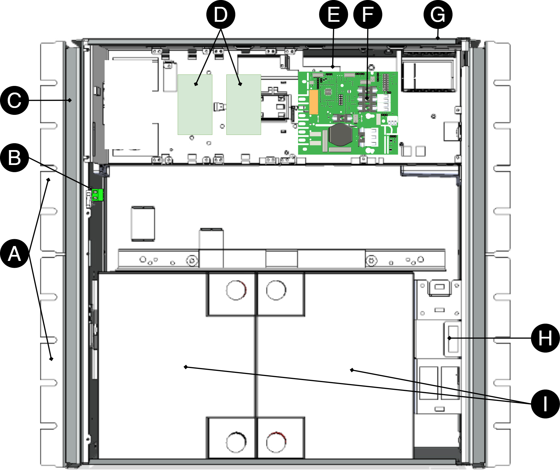
Letter | Explanation |
|---|---|
A | Bracket, reversible for mounting in a wall or 19" rack. |
B | Optional: Tamper switch |
C | Cabinet in powder-coated sheet metal. |
D | Space for optional cards |
E | Power supply, located on the back in some configurations. |
F | Cable entries. |
G | Motherboard. |
H | Lockable door. |
I | Space for batteries. |
Enclosures
General assembly instructions
Mounting - wall mounting
Enclosure must be mounted vertically.
For good ventilation, at least 100 mm of free space should be provided above and on the sides of the enclosure. Do not block the flow of air on the sides
The device should be mounted at a comfortable working height, normally between 1.4 and 1.8 m.
Recommended distance between screw head and wall should be 1.5-2 mm.
Avoid placement in direct sunlight, near heat sources, or in environments with high humidity or dust.
Installation shall be carried out in accordance with the applicable installation rules and by a competent installer.
Indoor mounting in 19" rack
The product should be mounted in a standardized 19" rack or cabinet with sufficient carrying capacity for the weight of the enclosure including batteries.
The device should be mounted at a comfortable working height, normally between 1.4 and 1.8 m.
The device is mounted horizontally in the rack with the included rack ears or corresponding brackets.
Check that the rack posts are properly aligned and that the spacing corresponds to the 19" standard (465—470 mm between the inner edge of the posts).
Use at least four mounting points (on each side) on the rack ears for stable attachment. Recommended screw size is M5 or M6
When assembling, cage nuts or locking washers should be used to ensure that the screws fit securely.
For good ventilation, at least 100 mm of free space should be provided above and below the unit. Do not block the air flow on the front or back.
Batteries should always be placed as directed and must not block ventilation openings or wiring.
Installation shall be carried out in accordance with the applicable installation rules and by a competent installer.
Mounting
Use the appropriate screw for mounting on a wall or in a 19" rack. Screws for mounting on a wall or in a rack are not included.
For wall mounting in concrete, concrete screws must be used. For rack mounting, M6 with basket nut is used
Screw length should be adjusted according to wall material and load. The specified screw length is the minimum allowable length
Bracket
The supplied brackets can be attached in two ways: When mounting on a wall, the brackets must sit backwards, against the wall. When mounting in a 19" rack, the bracket must sit at the front of the unit.
Letter | Explanation |
|---|---|
A | Bracket is pushed in from the bottom up. Slide the top bracket in first. |
B | Clip clicks in when bracket is pushed in correctly. |
Batteries - placement and connection
Connection of batteries in FLX S, FLX M and FLX L
Battery wiring is mounted on the circuit board upon delivery. Pictures below only show how to connect wiring.
Place the batteries in the cabinet with the battery terminals facing outwards.
Connect the battery cable. Red cable on + and black cable on -.
Plug in battery fuse.
If possible, disconnect mains voltage when replacing the battery.
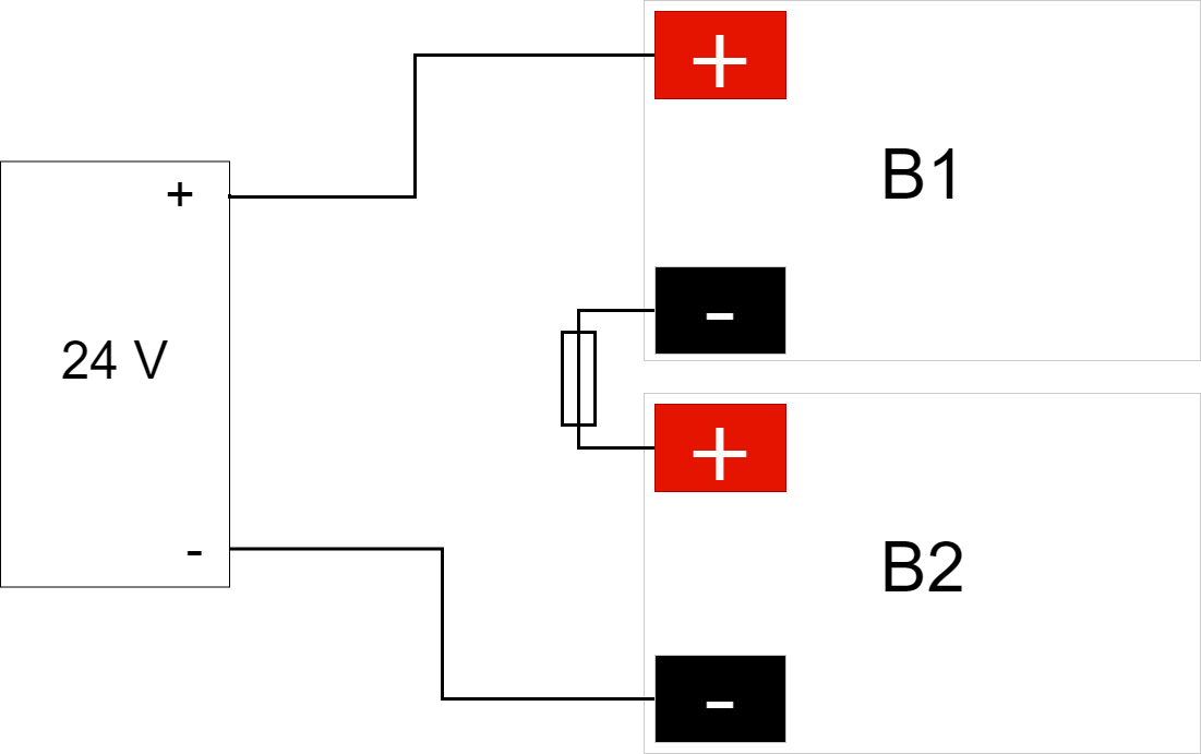
Connect the terminals correctly so that you do not damage the equipment.
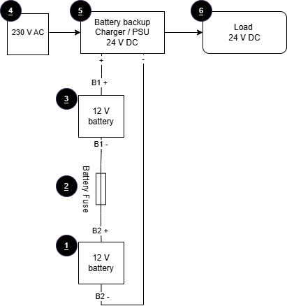
No. | Explanation |
|---|---|
1 | Battery 2. |
2 | Battery fuse. |
3 | Battery 1. |
4 | Incoming mains voltage, 230 V AC. |
5 | Rectifier 24 V DC. |
6 | Load, 24 V DC. |
Note when connecting batteries
When connecting batteries to NEO, cables with flat pins must not be used. In the picture marked with "NOVA ONLY"
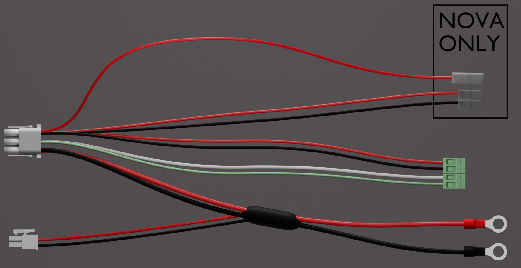
Motherboard description
Connect in this order
To minimize the risk of short-circuit errors, connect the components to the motherboard in the following order.
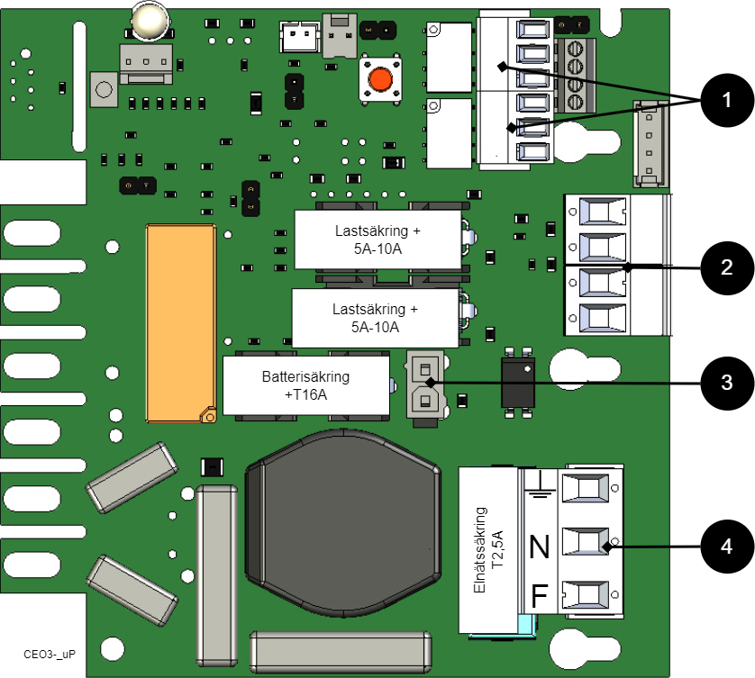
Nr | Explanation |
|---|---|
1 | Connect alarm. |
2 | Connect load. |
3 | Connect batteries |
4 | Connect mains. |
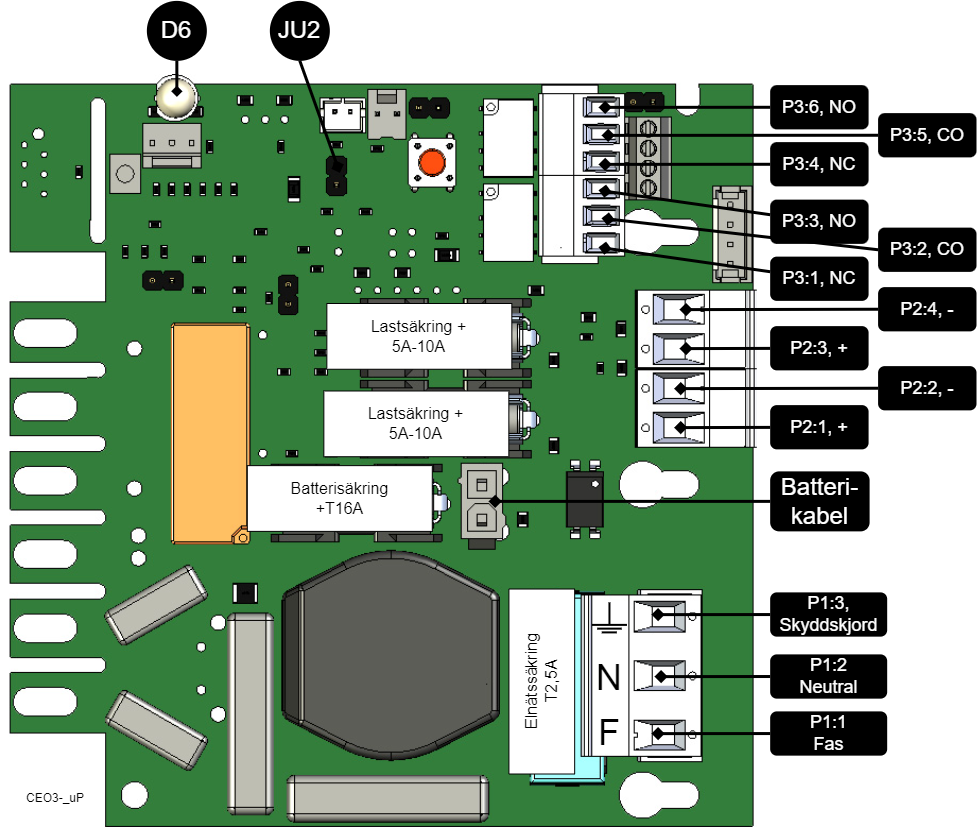
On PCB | Explanation |
|---|---|
D6 | Indicator diode. |
JU2 | Jumper for alarm control. When the jumper is mounted, the alarm limit is lowered. |
P1:1-3 | Mains connection, F, N, PE. |
P2:1-2 | Load output, + / -. |
P2:3-4 | Load output, + / -. |
P3:1-3 | Alarm output, NC, CO, NO. |
P3:4-6 | Alarm output, NC, CO, NO. |
Connect alarm on P3
Alarm is connected to terminal P3
P3:1-6 | Explanation |
|---|---|
Sum alarm | |
P3:1 | NC |
P3:2 | CO |
P3:3 | NO |
Sum-alarm* | |
P3:4 | NC |
P3:5 | CO |
P3:6 | NO |
Total alarm: Broken fuse on load, broken fuse from external distribution board, broken battery fuse, low battery voltage in battery operation, batteries not connected, overvoltage.
Connect load
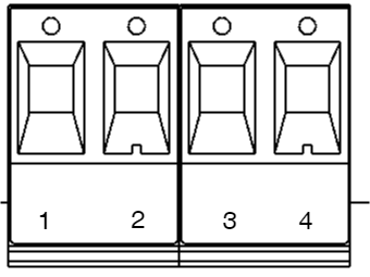
Circuit board number | Explanation |
|---|---|
P2: 1 | Connection for load 1 + |
P2: 2 | Connection for load 1 - |
P2: 3 | Connection for load 2 +. |
P2: 4 | Connection for load 2 -. |
Max current
The maximum current must not be exceeded. Max current is indicated on the rating plate on the device.
Danger
Mains voltage must be disconnected when working with stripped cables. It is the installer's responsibility to ensure that the correct skills are available for connecting 230 V to the unit. Maximum cable area is 4 mm2
Connect mains
Before connecting, the supply circuit should be disconnected and voltage-free. Verify that the conductor area and cable type meet the applicable installation rules and that the strain relief and insulation levels comply with the requirements for 230 V AC
After connection, all screw connections should be checked and tightened. Tensioning shall only take place after mechanical protection, caps and housing have been reassembled and comply with the contact protection according to EN 62368-1
Secure F and N with cable ties.
Important
Protective earth (PE) must be connected to the PE terminal on the motherboard. The motherboard is grounded via its mounting points in the enclosure, ensuring proper potential equalization between PCB and enclosure. Also the cover is grounded through ground cable/earth braid between cover and enclosure to maintain continuity and EMC
Mains wiring must be kept separate from other wiring to avoid EMC interference.
The protective earth (PE) must be connected to the PE terminal on the motherboard. The motherboard is grounded via its mounting points in the enclosure, ensuring correct equipotential bonding between the circuit board and the enclosure. The cover is also grounded via a grounding cable / grounding braid between the cover and the enclosure to maintain continuity and EMC function.
Check that the marking on the circuit board matches the wiring order on the terminal block.
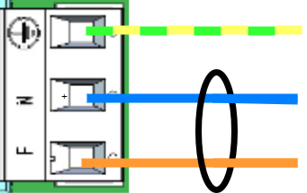
Connect the mains cable to the terminal block before it is re-inserted into the motherboard. Secure L (F in picture) and N with cable ties for electrical safety.
Letter | Explanation |
|---|---|
L | Fas |
N | Neutral |
PE |
Control alarm limit
Alarm for low battery voltage in battery operation can be controlled.
Fuses
Unit | Fuse | Type | Explanation |
|---|---|---|---|
All units | F1 | T2,5A | Mains fuse |
| F2, F6 | T10A | Load fuse + |
All units | F7 | T16A | Battery fuse |
Warning for replacing fuses (current strength, A)
There is a risk of damage if the fuse is changed to a larger one than what the unit is delivered with. The function of the fuse is to protect the connected load and cables against damage and fire. It is not possible to change the fuse to a larger one to increase the power output.
Commissioning - how to start the unit
Connect in this order
To minimize the risk of short-circuit errors, connect the components to the motherboard in the following order.
Nr | Explanation |
|---|---|
1 | Connect alarm. |
2 | Connect load. |
3 | Connect batteries |
4 | Connect mains. |
The unit works normally when the indicator LED on the outside of the cabinet door lights up with a solid green light. See front panel for other status indications.
It may take up to 72 hours for the batteries to be fully charged.
Alarm displayed on cabinet door
In normal mode, the indicator LED shows a solid green light.
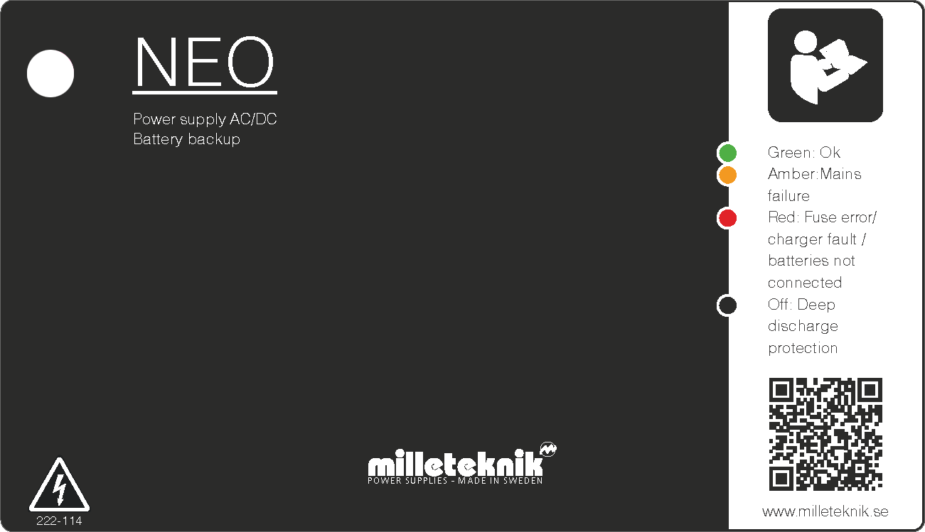 |
The indicator diode (LED) shows | Explanation |
|---|---|
Solid green light | Normal operation. |
Slow green flashes | Not available for NEO. |
Fast green flashes | Not available for NEO. |
Solid amber light | Mains failure. |
Slow amber flashes | Not available for NEO. |
Rapid amber flashes | Not available for NEO. |
Solid red light | Fuse error / charger fault / batteries not connected. |
Slow red flashes | Not available for NEO. |
Rapid red flashes | Not available for NEO. |
No light / off | Deep discharge protection is activated. (System shutdown). |
When operating system: If the indicator LED is off, deep discharge protection has been activated.
Notice
If the indicator light flashes every 15 seconds, the battery is fully charged and the charge is in rest phase to extend battery life. In the event of a power failure during the rest phase, the battery backup switches to battery operation as usual
NEO Product Sheet
NEO Battery backup with more alarm functions
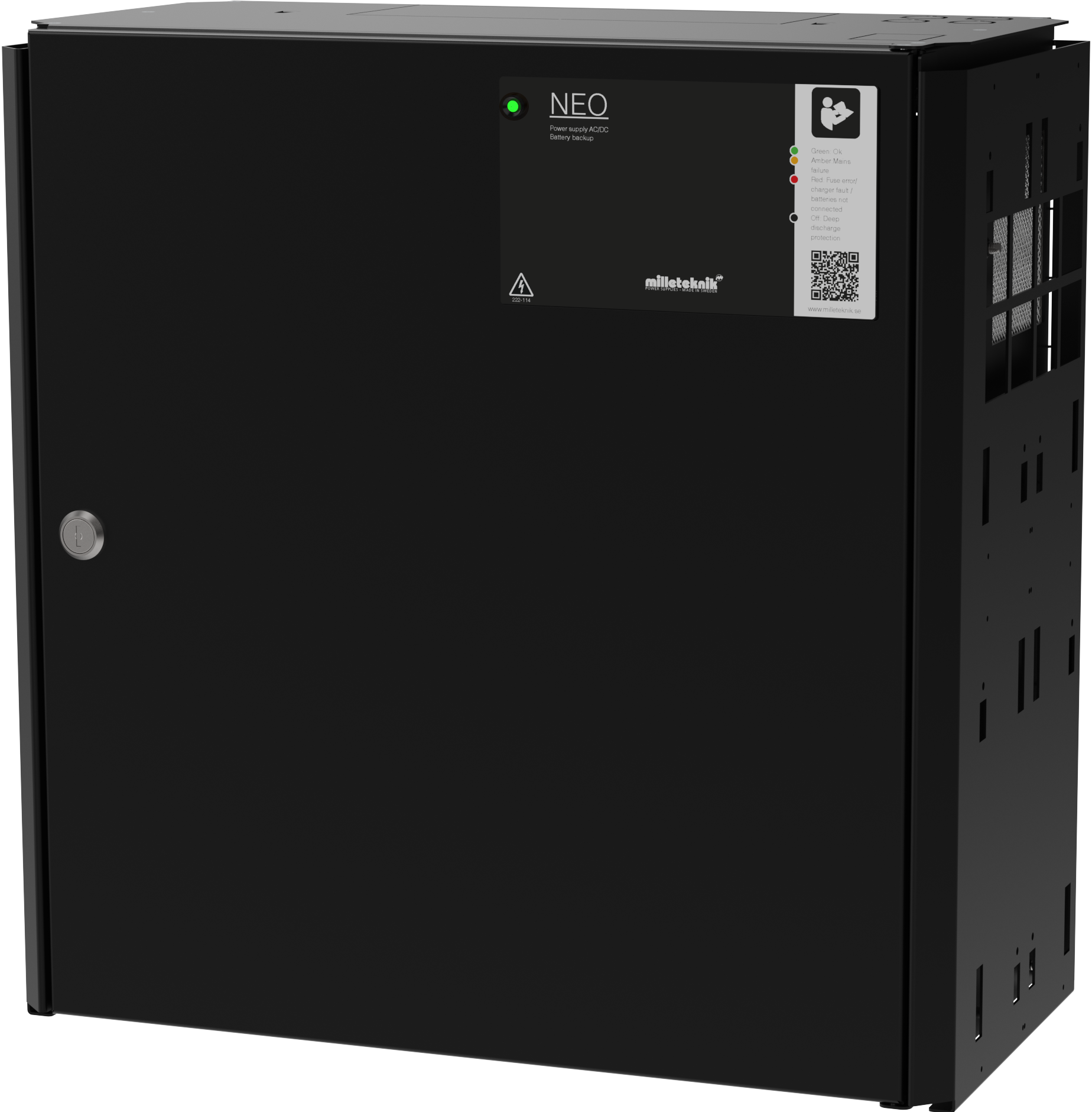
NEO FLX L is mounted on a wall or in a 19" rack.
Technical specifications
These technical specifications are subject to change without notice.
Product Identification
Product designation | Article number | E-number (SE) |
|---|---|---|
NEO 24V 10A FLX L | FL01N10224P100 | 52 136 97 |
NEO battery backup for security installations
NEO is normally used in facilities where the requirements are higher regarding greater flexibility, more alarm functions, longer backup operating times or when the battery backup needs to handle higher loads. The NEO series offers controlled charging (intelligent charging), which means that when the batteries are fully charged, they will be electronically disconnected for standby mode for up to 20 days or when the batteries have reached 26.7 V (24 V). By discharging the batteries and recharging them continuously (instead of never using them), the system extends the life of the battery by up to 50%. The batteries automatically connect in less than 50 microseconds when needed.
Flexibility
NEO FLX S can have an extra battery box. NEO FLX M and NEO FLX L with 1-4 extra battery boxes. NEO FLX M and NEO FLX L with battery shelves in 19 ”rack *. * The battery boxes and shelves are connected via a 9-pin connector. The battery box has room for up to 2 pcs. 45 Ah batteries per battery box. Battery shelves have room for 2 pcs. 45 Ah batteries (Medium) and up to 2 pcs. 150 Ah batteries (Large) per each battery shelf.
Area of use
NEO supplies power to access systems, alarm systems or other security products in a building that are powered by 24 V DC. The rectifier in the power supply converts 230 V DC down to 24 V DC. Batteries, for example the access system, continue when the power grid goes down. Long life, energy efficient and support is available if something goes wrong, now or in 10 years.
Fixed installation
The product is intended for fixed installation. The battery backup must be installed by a qualified installer.
Regulations and certifications
Requirements that the product meets
EMC: | EMC Directive 2014/30/EU |
Electricity: | Low Voltage Directive 2014/35/EU |
CE marking: | Regulation (EC) No 765/2008 |
Machinery Directive | The product is part of electrical systems, is subject to the relevant electrical and safety directives and is not a machine according to the Machinery Directive (2006/42/EC). |
Ecodesign | Milleteknik's products are intended for professional use and are therefore not directly covered by the Ecodesign Regulation (EU 2019/1782). As some components may be covered, we nevertheless disclose relevant information to give our customers confidence in their choice |


Expected operating time in the event of a power failure ( with new batteries)
System voltage | Number of batteries | Battery type | Unit + battery box * | Load: 2 A | Load: 4 A | Load: 8 A | Load: 10 A | Load: 14 A | Load: 18 A |
|---|---|---|---|---|---|---|---|---|---|
24 V | 2 pcs. | 45 Ah | 1+0 | 21 h | 12 h | 4 h | 3 h | 2 h | 1.5 h |
24 V | 4 pcs | 45 Ah (90 Ah) | 1+1 | 42 h | 20 h | 12 h | 8 h | 5 h | 2.5 h |
24 V | 6 pcs | 45 Ah (135 Ah) | 1+2 | 64 h | 30 h | 15 h | 12 h | 9 h | 6 h |
24 V | 8 pcs | 45 Ah (180 Ah) | 1+3 | 82 h | 42 h | 20 h | 16 h | 12 h | 10 h |
24 V | 10 pcs | 45 Ah (225 Ah) | 1+4 | 108 h | 54 h | 26 h | 20 h | 15 h | 13 h |
* Example: 1 + 2 means that there is 1 battery backup with 2 battery boxes connected. 1 + 0 means that it is a battery backup without a battery box. | |||||||||
Circuit boards - Technical data
Technical data: CEO 3
Info | Explanation |
|---|---|
Article name | CEO3-ECO |
Product description | CEO 3 is the next generation circuit board for simpler battery backups. Advanced functions that were not previously possible in simpler battery backups are now available as standard. CEO 3 is manufactured with fewer components than before, which reduces the environmental impact. |
Measure | 120 x 55 mm x 52 mm |
Own consumption | 50 mA |
Fuses | See table: Fuses. |
Outputs | Output: two load outputs. |
Insurance | Load output: + secured. |
Max load | Maximum load is 10 A per load output (T2A is mounted from the factory) and the card's total load must not exceed 16 A. |
Alarm outputs | Alarm outputs: Sum alarm in case of fuse fault, see indication below. Alarm on potential-free relay contact. |
Alarm | Sum alarm, Mains failure, fuse failure, charger failure, batteries not connected. |
Alarm via | Triggered load securing, potential-free shifting, CO / NO. |
Indication | Display showing operating status, alarms and faults. Operating indication: one indication diode per load output +/-. Solid green light = normal operation. |
Control alarm limit with JU2
Control alarm limit
Alarm for low battery voltage in battery operation can be controlled.
Fuses
Unit | Fuse | Type | Explanation |
|---|---|---|---|
All units | F1 | T2,5A | Mains fuse |
| F2, F6 | T10A | Load fuse + |
All units | F7 | T16A | Battery fuse |
Warning for replacing fuses (current strength, A)
There is a risk of damage if the fuse is changed to a larger one than what the unit is delivered with. The function of the fuse is to protect the connected load and cables against damage and fire. It is not possible to change the fuse to a larger one to increase the power output.
Power supply
Power supply - Technical Data LRS-150-24
In: |
|---|
Info | Explanation |
|---|---|
Output voltage | 27.3 V |
Output current: | 0 A - 6.5 A |
Output voltage, ripple | 200 mVp-p |
Overvoltage | 28.8 V - 33.6 V |
Voltage recharge, ripple / current limitation | Less than 0.6 Vp-p |
Efficiency | 89% |
Current limitation | 110% - 140% |
Constant voltage | +/- 0.5% |
Regulatory accuracy | + / - 1.0% |
Input current (230 V) | 1,7 A |
Mains voltage frequency | 47 Hz- 63 Hz |
Mains voltage | 230 V AC - 240 V AC |
Brand effect | 156 W |
Temperature range | -30°C - +70°C |
Humidity range | 20% - 90% RH non-condensed |
Power supply - Technical Data RSP-320-24
In: |
|---|
NEO 24V 10A FLX L |
Info | Explanation |
|---|---|
Output voltage | 27.3 V |
Output current | 0 A - 13.4 A |
Output voltage, ripple | 150 mVp-p |
Overvoltage | 27.6 V - 32.4 V |
Voltage recharge, ripple / current limitation | Less than 1.2 Vp-p |
Efficiency | 89% |
Current limitation | 105% - 135% |
Constant voltage | +/- 0.5% |
Regulatory accuracy | +/- 1.0% |
Input current (230 V) | 2 A |
Mains voltage frequency | 47 Hz- 63 Hz |
Mains voltage | 230 V AC - 240 V AC |
Brand effect | 321.6 W |
Temperature range | -30°C - +70°C |
Humidity range | 20% - 90% RH non-condensed |
Technical data enclosures
Enclosures - Technical Data FLX L
Info | Explanation |
|---|---|
Name | FLX L |
Enclosure class | IP 32 |
Measure | Height: 444 mm, width 438 mm, depth 212 mm |
Height units | 10 HE |
Mounting | Wall or 19 "rack |
Ambient temperature | + 5 ° C - + 40 ° C. For best battery life: + 15 ° C to + 25 ° C. |
Environment | Environmental class 1, indoors. 20% ~ 90% relative humidity |
Material | Powder coated sheet |
Color | Black |
Cable entries, number | 4 |
Batteries that fit | 2 st 12 V 45 Ah |
Place for fan | Yes |
Link to the latest information
Products and software are subject to updates, you will always find the latest information on our website.
Warranty, support, country of manufacture and country of origin
Warranty
The product has a two-year warranty, from the date of purchase (unless otherwise agreed). Support during the warranty period can be reached at support@milleteknik.se or telephone, +46 31-34 00 230. Compensation for travel and / or working hours in connection with locating faults, installing repaired or replaced goods is not included in the warranty. Contact Milleteknik for more information. Milleteknik provides support during the product's lifetime, however, no later than 10 years after the date of purchase. Switching to an equivalent product may occur if Milleteknik deems that repair is not possible. Support costs may (at Milleteknik's discretion) occour after the warranty period has expired.
Support
Do you need help with installation or connection?
You will find answers to many questions at: www.milleteknik.se/support
Phone: +46 31-340 02 30
Support is open: Monday-Thursday 08:00-16:00, Fridays 08:00-15:00. Closed 11:30-13:15.
Spare parts
Contacted support for questions about spare parts.
Support after the warranty period
Milleteknik provides support during the life of the product, but no longer than 10 years after the date of purchase. Replacement for an equivalent product may occur if the manufacturer deems that repair is not possible. Costs for support and replacement are added after the warranty period has expired.
Questions about product performance?
Contact sales: 46 31-340 02 30, e-mail: sales@milleteknik.se
Contact us
Milleteknik AB
Ögärdesvägen 8 B
S-433 30 Partille
Sweden
+46 31-34 00 230
www.milleteknik.se
Country of manufacture
Country of manufacture / country of origin is Sweden. For more information, contact your seller.
Designed and produced by: Milleteknik AB
Designed and produced by Milleteknik AB
Batteries - recommended, not included
Batteries are not included they are sold separately
Batteries are sold separately.
45 Ah, 12 V AGM battery
Fits in | Number of batteries |
|---|---|
NE0 24V 10A FLX L | 2 |
Battery type | Excitement | Ah |
|---|---|---|
Maintenance-free AGM, lead-acid battery. | 12 V | 45 Ah |
Article number | E-number | Article name | Terminal | Measure. Height width depth | Weight per piece | Make |
|---|---|---|---|---|---|---|
MT113-12V45-01 | 5230546 | UPLUS 12V 45Ah 10+ Design Life battery | M5 Bult | 197x165x170 mm | 14.5 kg | UPLUS |
Address and contact details
Milleteknik AB |
Ögärdesvägen 8 B |
S-433 30 Partille |
Sweden |
+46 31 340 02 30 |
info@milleteknik.se |
www.milleteknik.com |