
Installation and commissioning
Instructions for installation and commissioning.
Product Identification
Product designation | Part number | E-number (SE) |
|---|---|---|
PoE Switch 8p PS UT S | PL02P00048P050P-UTS | 51 73 418 |
PoE
If
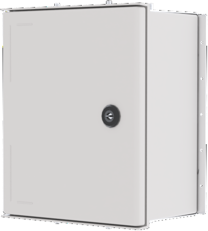
PoE Switch 8p PS OUT S is a power supply with PoE switch for outdoor use. Built to withstand Nordic conditions - summer as winter. The product is different from indoor battery backups from Milleteknik and some features have been added and
Revisions and the edition of this document
The current and most recently published edition of this document is available at www.milleteknik.com.
The validity of this document can not be guaranteed, as new editions are published without prior notice.
Original instructions for use: Swedish.[1].
Instructions for use, technical data and translations thereof may contain errors. It is always the responsibility of the installer to install the product in a safe manner.
Symbols
Symbols | Name | Explanation |
|---|---|---|
 | Warning | Risk of electric shock, improper installation or hot surfaces. Appears in some manuals |
 | Note | Used for supplementary information that clarifies the text. |
 | Caution/Important | Indicates the risk of equipment damage or malfunction. Also used for information that is important but not security-related |
 | Tips | Displays practical advice or shortcuts for installation, operation, or service. |
 | CE marking | The product complies with applicable EU directives and harmonised standards. |
 | Read the manual | Please read manual before installation and service. |
 | Do not dispose of in household waste | The product is covered by the WEEE Directive and must not be disposed of with household waste, it must be recycled and delivered to a recycling centre. |
 | Recycling | Packaging, products and other materials that do not contain electronics must be recycled in accordance with local environmental regulations. |
Installation — general information
Installation shall be carried out by a competent electrician in accordance with the applicable national electrical installation rules.
The product is of protection class I and must be connected to a grounded 230 V AC circuit.
A mains disconnect switch according to IEC 60947-1 shall be provided in the fixed installation. The switch should be easily accessible and clearly marked with its function.
The area of the supply cable shall be at least 1,0 mm² and fitted with a fuse T 2,5 A (slow-blown) or equivalent.
AC and low voltage cables must not be pulled together. Keep separate cable chutes or bundles
Check that protective earth (PE) is properly connected before turning on voltage.
Ensure free air circulation around the enclosure at least 100 mm, unless otherwise specified. Ventilation openings must not be covered.
The product is intended for outdoor installation.
These general requirements apply to all Milleteknik products with 230 V mains connection.
Requirements for mains disconnect switch, fuse and cable cross-sectional area
In order to comply with applicable electrical safety requirements, the installation shall be equipped with a mains disconnect switch according to IEC 60947-1.
Component | Requirements |
|---|---|
Main switch | A mains disconnect switch according to IEC 60947-1 shall be included in the installation and be easily accessible. Separated phase (L) and neutral (N) |
Fuse | The supply circuit shall be protected by a fuse or circuit breaker with rated current according to the product specification (normally T 2,5 A slow-blow or equivalent). Refer to the device's nameplate. |
Fuses | Approved type according to IEC 60127. |
Cross-sectional area (230 V) | At least 1,0 mm2 |
Cable length | In the case of longer wiring, voltage drops should be taken into account so that the operating voltage does not fall below 230 V ± 10% at the unit. |
Strain relief | All cables must be properly secured and strain relief checked before energizing the unit. |
These requirements apply to all Milleteknik products with 230 V mains connection.
Enclosures
General assembly instructions
Outdoor mounting on pole
The product is intended for mounting on a pole with rails or corresponding fastening parts.
Enclosure to be mounted vertical.
For good ventilation, at least 100 mm of free space should be provided around the enclosure.
Use rails and fasteners that are compatible with the weight and mounting pattern of the product.
Install the rails in the product before installing the post brackets or pipe clamps.
Place pipe clamps or corresponding fastening parts around the post and connect them to the mounting points of the rails.
Check that the product is aligned and mounted in a vertical position before tightening.
The diameter and material of the post should be suitable for the selected type of fastening detail.
Tighten all screws and nuts according to the recommendations of the fastening details.
Ensure that the product is firmly fixed and cannot rotate or slide on the post after assembly.
Cable connections should be oriented downwards or according to the specific installation instructions of the product.
Avoid locations where water can flow directly onto the enclosure from surfaces above.
Avoid placement in direct sunlight or near heat sources.
Installation shall be carried out in accordance with the applicable installation rules and by a competent installer.
Mounting
Use the appropriate screw for mounting on a wall or in a 19" rack. Screws for mounting on a wall or in a rack are not included.
For wall mounting in concrete, concrete screws must be used. For rack mounting, M6 with basket nut is used
Screw length should be adjusted according to wall material and load. The specified screw length is the minimum allowable length
Mounting holes, spacing and ø.
Mounting options and accessories
To ensure a smooth installation, we offer several custom mounts for our UT series enclosures (S, M and L). In the matrix below you will see which options are compatible
Please note that a wall mount is always included as standard with all models. For pole mounting or needing extra sun protection, separate optional kits are required
Enclosure | Wall Bracket | Pole Bracket | Sun protection | Camera and pole mount (upcoming) | Speaker Bracket |
|---|---|---|---|---|---|
OUT S | Included | Pole Mount Kit for UT S and UT M | Sun Shield Kit | Not Possible | Not Possible |
Accessories | Enclosure |
|---|---|
Pole Mount Kit for UT S and UT M | UT S and UT M |
Sun Shield Kit | UT S, UT M and UT L |
Mounting on pole
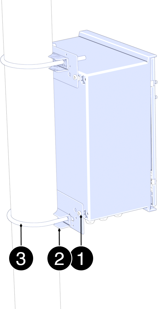
Mounting on pole
See component overview for screw, nut, washers and spacers.
No. | Explanation |
|---|---|
1 | Fastening plate. |
2 | Counter. |
3 | U-bolt. |
Assemble in this order:
Place the mounting plates (3) on the upper and lower attachment points of the enclosure and attach them lightly with the screws provided. Do not tighten finally yet.
Pass the lower U-bolt (2) around the post and through the holes in the lower mounting plate. Install washers and nuts. Tighten lightly.
Pass the upper U-bolt (2) around the post and through the holes in the upper mounting plate. Install washers and nuts
Adjust the position of the enclosure so that it is in solder and centered toward the post.
Tighten all nuts in sequence: — lower U-bolt — upper U-bolt — screws to the mounting plates
Check the attachment by lightly loading the enclosure forward/backward to ensure stable mounting.
Component overviews
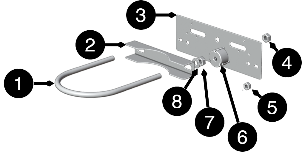
Component overview Mounting Kits
No. | Explanation | Size | Number |
|---|---|---|---|
1 | Fixing plate | 125mm | 2 |
2 | U-bolt for pole | - | 2 |
3 | Washers and nuts | - | 2 |
4,7 | Nut | M10 | 4 |
5 | Nut | M6LM | 8 |
6 | Distance | Ø 36 mm, depth 20 mm | 4 |
8 | Washer | 10 (5x20x2) | 4 |
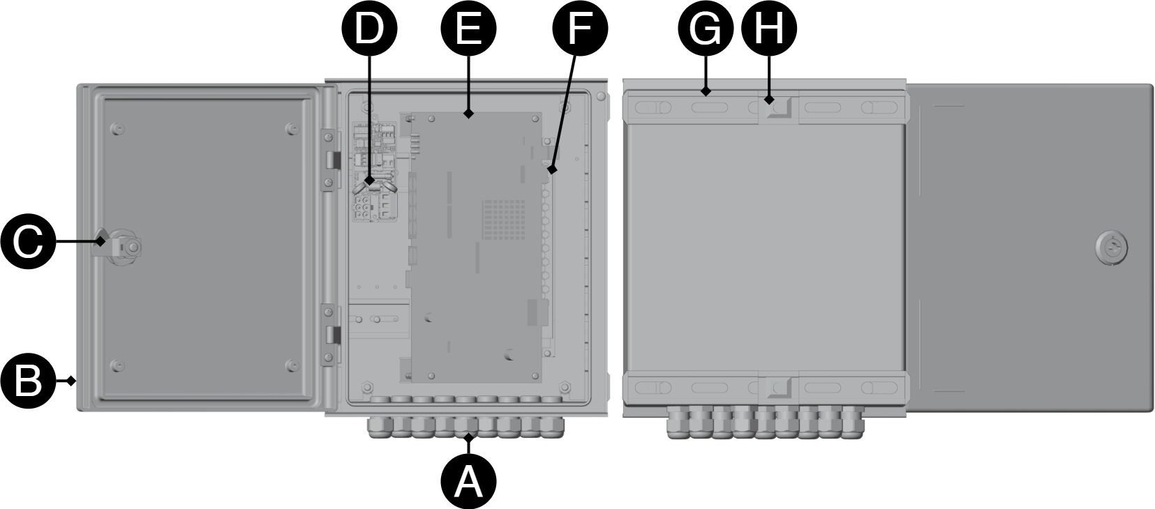
Component overviewNOVA FLX L
Letter | Explanation |
|---|---|
A | Cable grommets. |
B | [sv] Anslutning för neutral (N) |
C | [sv] Anslutning för fas (L) |
D | [sv] Anslutning för jord (PE) |
E | Door. |
F | Lock. |
G | Plugging/lightning protection board. |
H | Poe card. |
I | Power supplies. |
Short description 230 V plug in, 24 V DC out and lightning protection
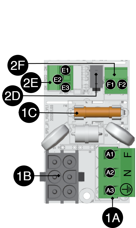
Designation | Explanation | |
|---|---|---|
1A | Connection 230 V AC inbound. | |
A1 | Phase (F) | |
A2 | Neutral (N) | |
A3 | Soil (PE) | |
1B | Connection to power supply. | |
1C | Net fuse. | |
Designation | Explanation | |
|---|---|---|
2D | 24 V DC power supply from power supply. | |
2e | Alarms | |
E1 | N.C. | |
E2 | COM | |
E3 | NOS | |
2F | 24 V out. | |
F1 | - | |
F2 | + | |
Switching on power supply
230 V is connected to terminal 1A.
Connect supply voltage, 230 V AC
Supply voltage is connected to the terminal block.
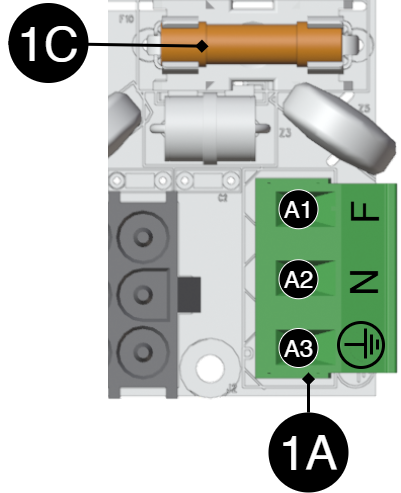
Designation | Explanation | |
|---|---|---|
1A | Connection 230 V AC inbound. | |
A1 | Phase (F) | |
A2 | Neutral (N) | |
A3 | Soil (PE) | |
1C | Net securing. | |
Short description for PoE switch 4p
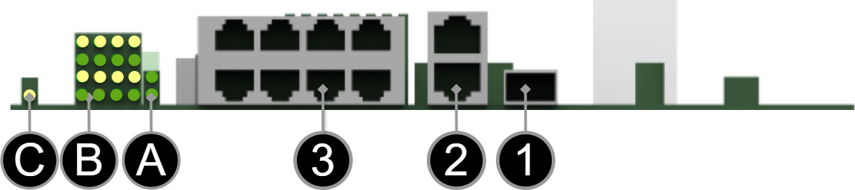
[sv] Notera att bilden kan vara vänd
Number/Letter | Explanation |
|---|---|
1 | SFP-port. |
2 | 2 pcs. RJ-45 ports for data, non-PoE, (not powered). |
3 | 8 pcs. RJ-45 powered ports for connecting |
A | Indication, green LED. This is only an indication of data transmission through the port and not the status of the connected device. This indication is for the two RJ-45 ports, (2), which are not PoE fed |
B | Indication, yellow LED lights up when PoE device is plugged in. This is only an indication that the port is connected and not the status of the connected device. Glows green when transferring data. This indication applies to the PoE fed RJ-45 ports (3). |
C | Glows yellow when the card is energized. |
How the PoE switch software is accessed
How the software is accessed in the PoE Switch
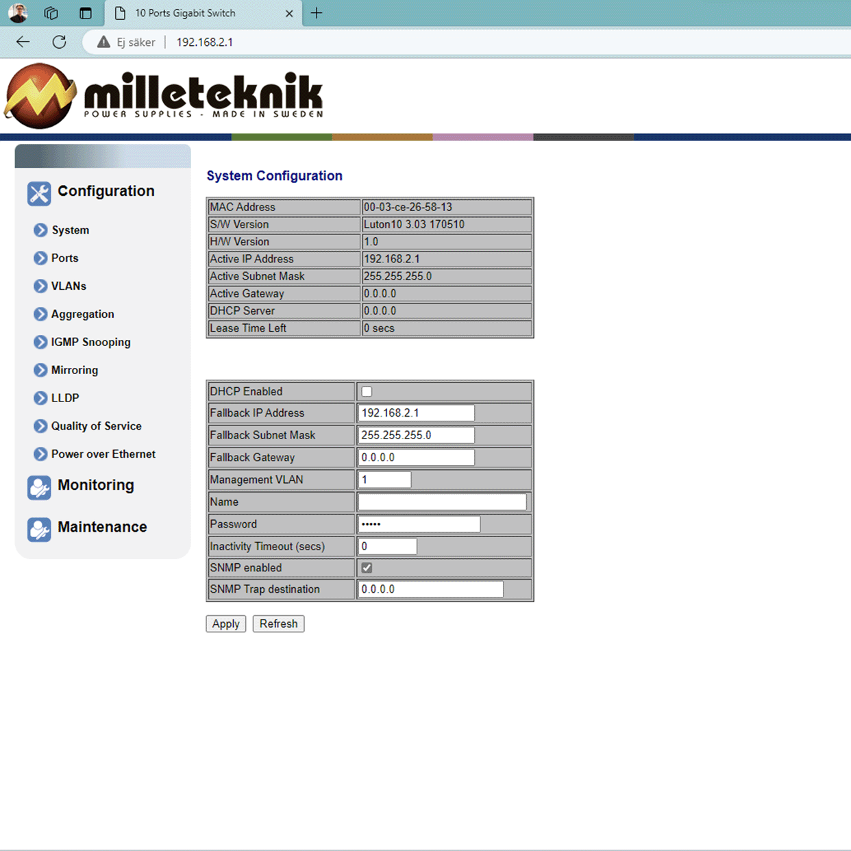
This section shows how to log in to the switch's configuration web page.
To configure the software in the switch, the correct IP address needs to be set on the computer.
Access to the switch's software is through a browser, (such as: Chrome, Edge, Firefox, etc.).
Follow the steps to access the switch's settings.
Note
The settings shown are settings for PC, (Windows 7 - Windows 11). Windows and names may vary between different versions of Windows. Unfortunately, we cannot provide support for settings of your computer.
Note
IP address of the switch (factory setting): 192.168.2.1
Password (factory setting): admin
Notice
The address of the PoE switch is: 192.168.2.1 and username and password are: admin/admin The IP address in the switch is static (fixed) and therefore the computer's IP address and subnet mask must be static.
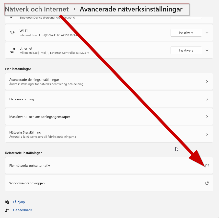
Open settings and go to Network and Internet -> Advanced network settings. Open more network card options.
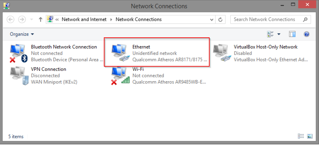
A Network Connections window will appear showing all available network connections on the computer. Double-click the network connection you use to connect to the switch.
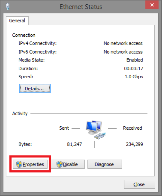
Ethernet status window appears. Click the button Characteristics as shown in the figure below.
Double-click: Internet Protocol Version 4 (TCP / IPv4).
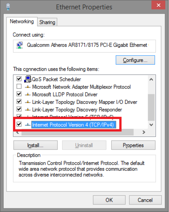
Set the computer's IP address and subnet mask as shown in the figure below. By default, the product's IP address be 192.168.2.1. You can set any IP address as long as it is not the same as your switch's IP address and is in the same network segment as your switch's IP address. Press on OK to apply the TCP/IPv4 settings you just made. Now you can connect to your switch using a web browser (Chrome, Edge or Firefox).
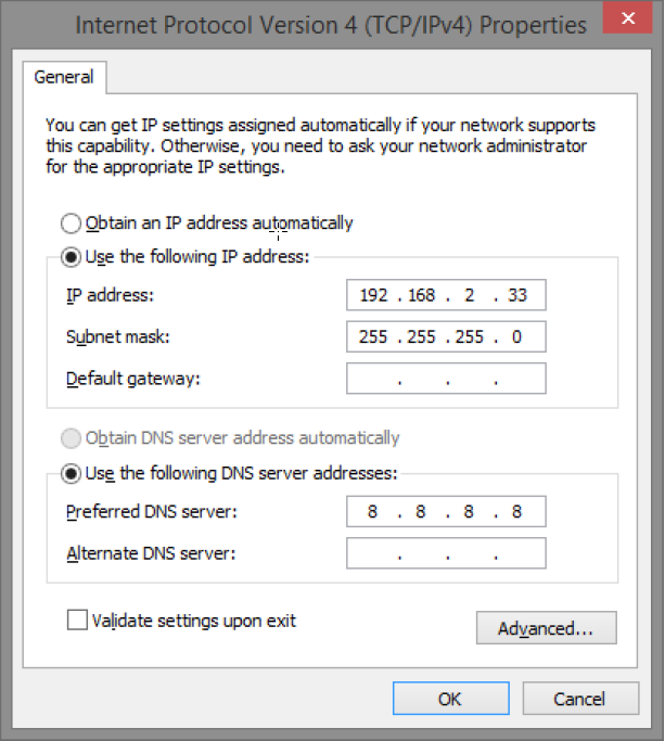
Connect an RJ-45 cable and connect to the PoE switch.
Log in to the PoE switch
Note
IP address of the switch (factory setting): 192.168.2.1
Password (factory setting): admin
Note
If you get a warning that the page is not secure/the connection is not private, click "advanced" and then "continue".
Start the browser on your computer.
Login to PoE switch.
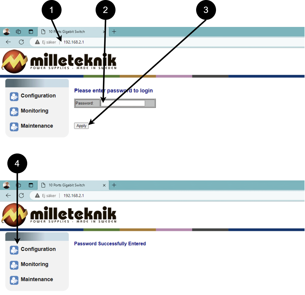 Table 15. Log in to the switch.
Number
Explanation
1
IP address of the PoE switch: 192.168.2.1
2
Password: admin
3
Apply = Ok
4
Menu in the PoE switch
Configuration
System, configuration
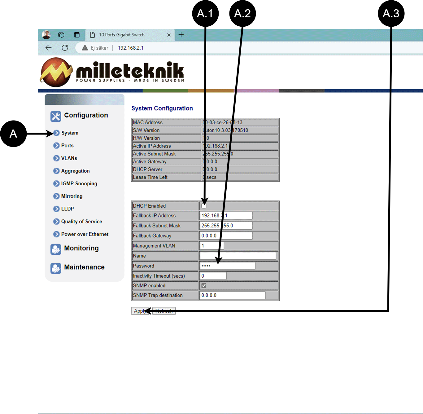
Letter, number | Explanation |
|---|---|
A | PoE switch system configuration page |
A.1 | Tick here if you are going to use DHCP, see warning below. |
A.2 | Changes the factory default password, (admin). |
A.3 | If you have made any changes, you need to click "Apply" to save the changes. |
Ports, configuration
Letter, number | Explanation |
|---|---|
B | Gates |
B.1 | This setting normally does not need to be changed. Select the speed of the PoE switch's ports. |
B.2 | This setting normally does not need to be changed. |
VLAN configuration
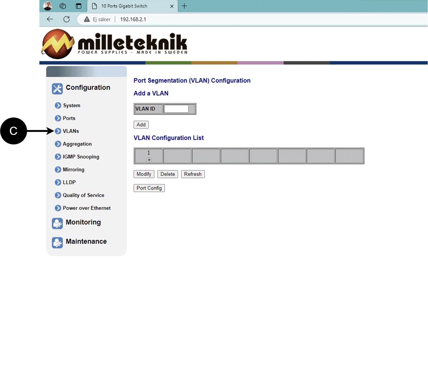
C: Configuration of Virtual LAN.
Aggregation, configuration
D: Load balancing between the ports.
IGMP Snooping, configuration
E: Switch that controls reception.
Mirroring, configuration
F: Mirroring of ports.
LLDP configuration
Letter, number | Explanation |
|---|---|
G | LLDP stands for "Link Layer Discovery Protocol", which is a network protocol standard used to discover and communicate information about network devices connected to the same Ethernet network. The protocol allows devices such as switches and routers to send and receive messages containing information about the device's identification, capabilities, and connection topology. |
G.1 | RX and TX are abbreviations used in electronics, communications, and computer networking to indicate the direction of data flow between devices. RX: The abbreviation "RX" stands for "Receive" or "Reception". It indicates that the device is receiving data or signals from another device. When a device has an RX input, it means that it is designed to receive data or information from a transmitting device. TX: The abbreviation "TX" stands for "Transmit" or "Transmission". It indicates that the device is transmitting data or signals to another device. If a device has a TX output, it means that it is designed to transmit data or information to a receiving device. These abbreviations are especially common when it comes to data communication, such as in the context of network cables where there are specific RX and TX wires that allow for two-way communication between devices. |
QoS, configuration
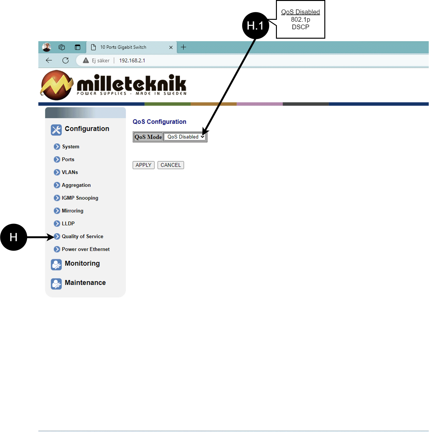
Letter, number | Explanation |
|---|---|
H | QoS gives different network traffic different priority, helping to ensure that important services are delivered with sufficient bandwidth and minimal delay even when the network is under load. |
H.1 | Sets whether QoS is active. |
PoE, configuration
Letter, number | Explanation |
|---|---|
I | Power over Ethernet |
I.1 | Turns PoE function/port on or off. Remember to press "Apply" to save changes. |
Monitoring
Statistics, overview
Letter, number | Explanation |
|---|---|
J | Statistics, overview |
J.1 | Traffic per port. |
Statistics, detailed
Letter, number | Explanation |
|---|---|
K | Detailed statistics |
K.1 | Select the port for which you want statistics. |
IGMP status
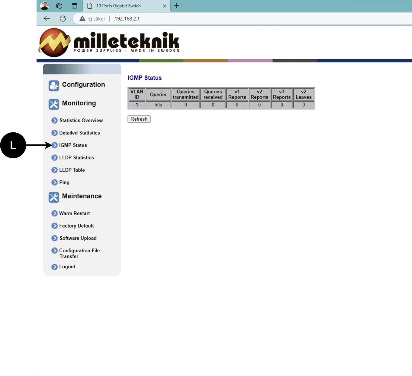
L: Status of IGMP
LLDP statistics
M: LLDP statistics
LLDP table
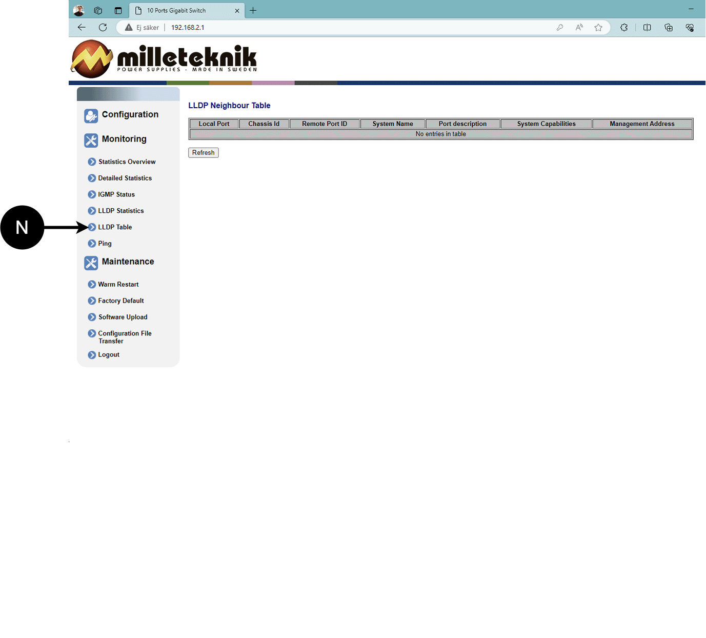
N: LLDP overview.
Ping
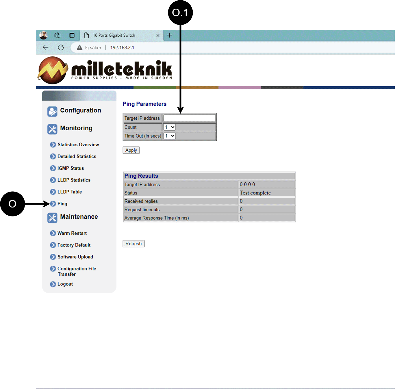
Letter, number | Explanation |
|---|---|
O | Ping |
[sv] O.1 | Input address to test the connection and response time. |
Maintenance
Reboot
Warning
Restart is done by PoE switch, battery backup is not restarted. Upon reboot, connected devices will lose connection. Alarm can be set to battery backup, but it disappears when the PoE switch is back on.
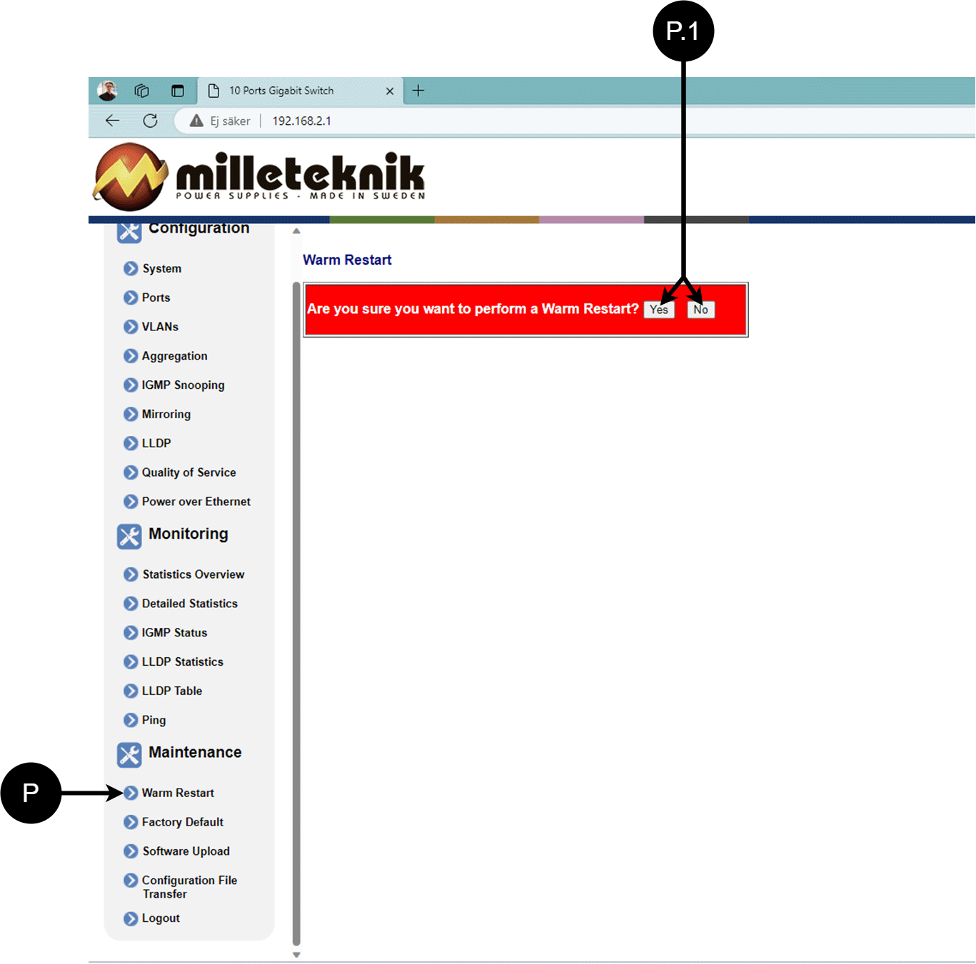
Letter, number | Explanation |
|---|---|
P | Rebooting the PoE switch. |
P.1 | Select "Yes" to reboot the switch. |
Factory reset
Warning
Factory reset is done by PoE switch. Battery backup is not restored. On reset, connected devices will lose connection. Alarm can be set to battery backup, but it disappears when the PoE switch is back on.
Factory reset of the switch can only be done from the software's (this) interface.
Recommendation: Keep IP address 192.168.2.1 and note password.
Important
During a factory reset, all settings, including IP settings, are lost. Save configuration before factory reset. See Upload new software
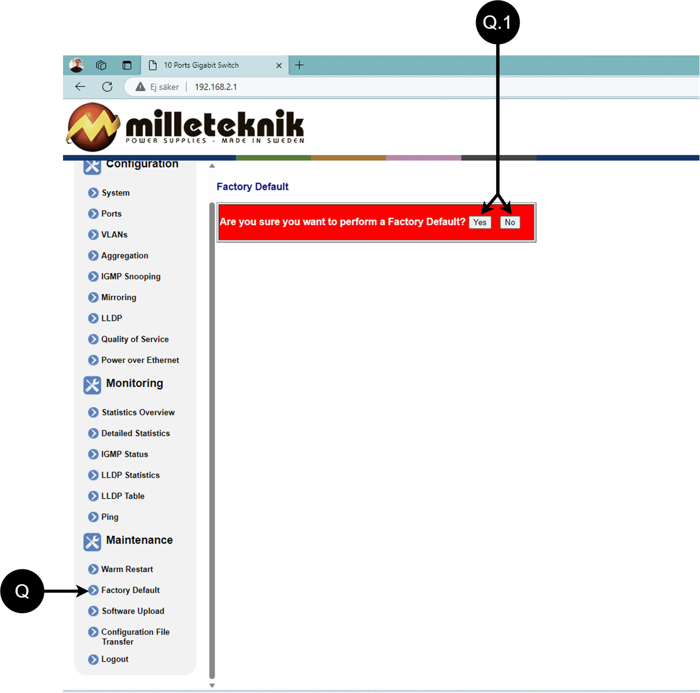
Letter, number | Explanation |
|---|---|
Q | Factory reset the PoE switch. |
Q.1 | Select "Yes" to factory reset the PoE switch. |
Upload new software
Warning
Only use software you received from Milleteknik's support. Milleteknik assumes no responsibility for software or consequences such as damage to the device or peripheral equipment or other damage that may arise from uploading unapproved software.
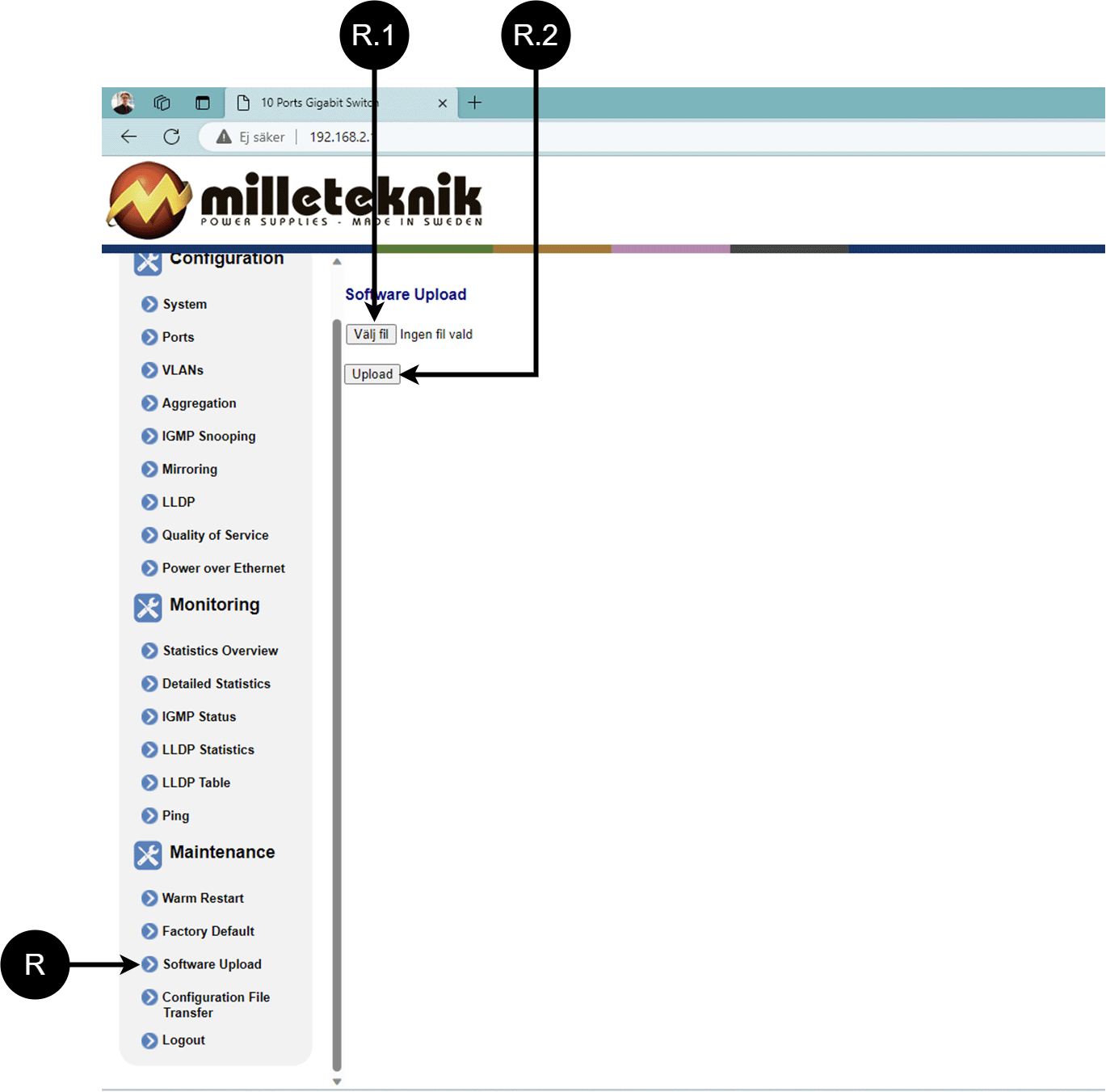
Letter, number | Explanation |
|---|---|
R | Upload new software to the Switch. |
R.1 | Navigate to the location on your computer where you saved the file. |
R.2 | Click "Upload" to upload the software. |
Load and save configuration file
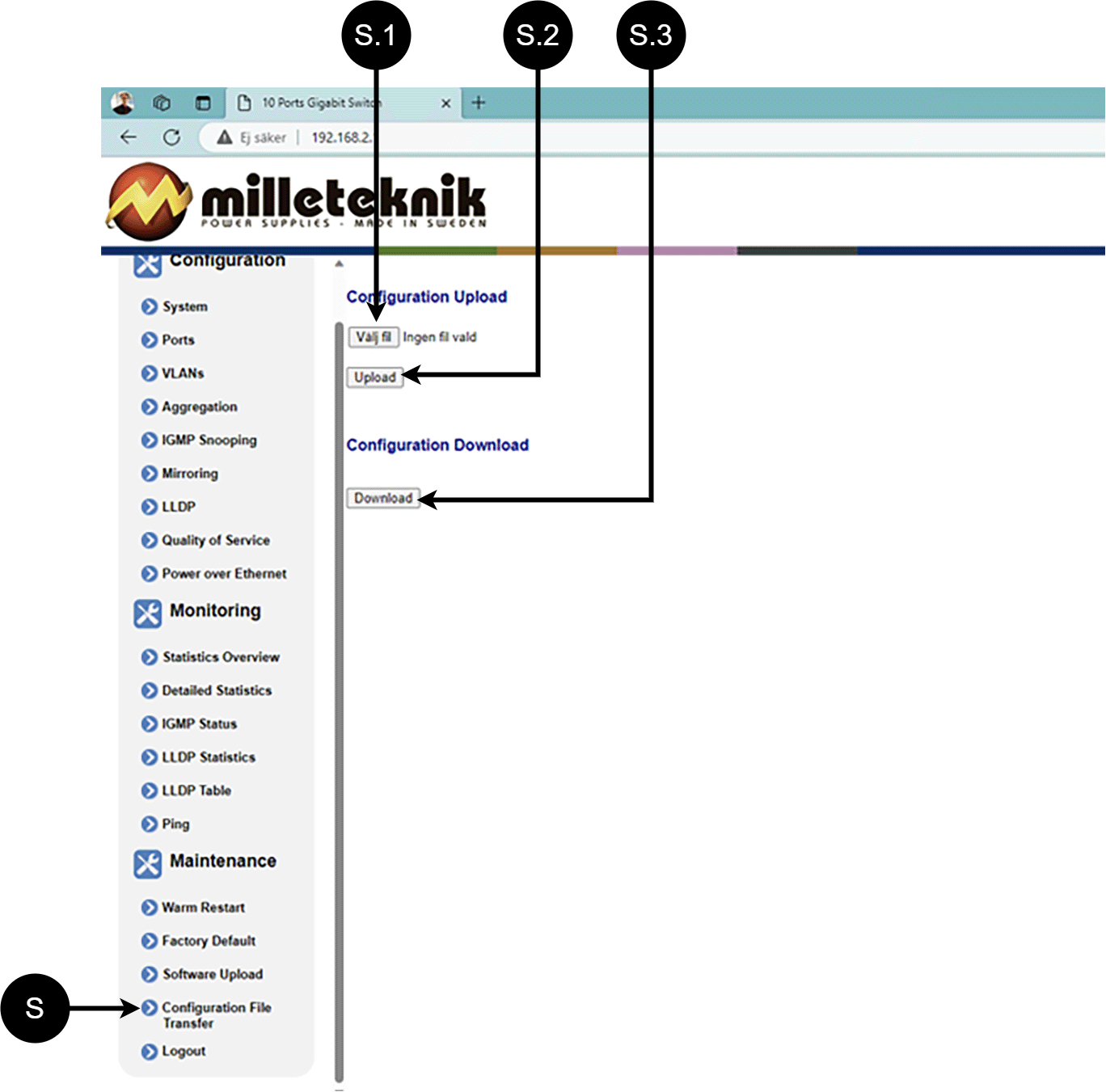
Letter, number | Explanation | ||||||||||||||||||||||||||||||||||||||||||||||||
|---|---|---|---|---|---|---|---|---|---|---|---|---|---|---|---|---|---|---|---|---|---|---|---|---|---|---|---|---|---|---|---|---|---|---|---|---|---|---|---|---|---|---|---|---|---|---|---|---|---|
S | Upload or download the switch's configuration. | ||||||||||||||||||||||||||||||||||||||||||||||||
S.1 | Select new configuration file. | ||||||||||||||||||||||||||||||||||||||||||||||||
S.2 | Upload new configuration file. | ||||||||||||||||||||||||||||||||||||||||||||||||
S.3 | Download configuration file to computer[a]. | ||||||||||||||||||||||||||||||||||||||||||||||||
[a] Newer Windows computers do not allow *.cfg files to be downloaded without additional approval in the browser when downloading. Antivirus programs may delete the file during download. | |||||||||||||||||||||||||||||||||||||||||||||||||
Sign out
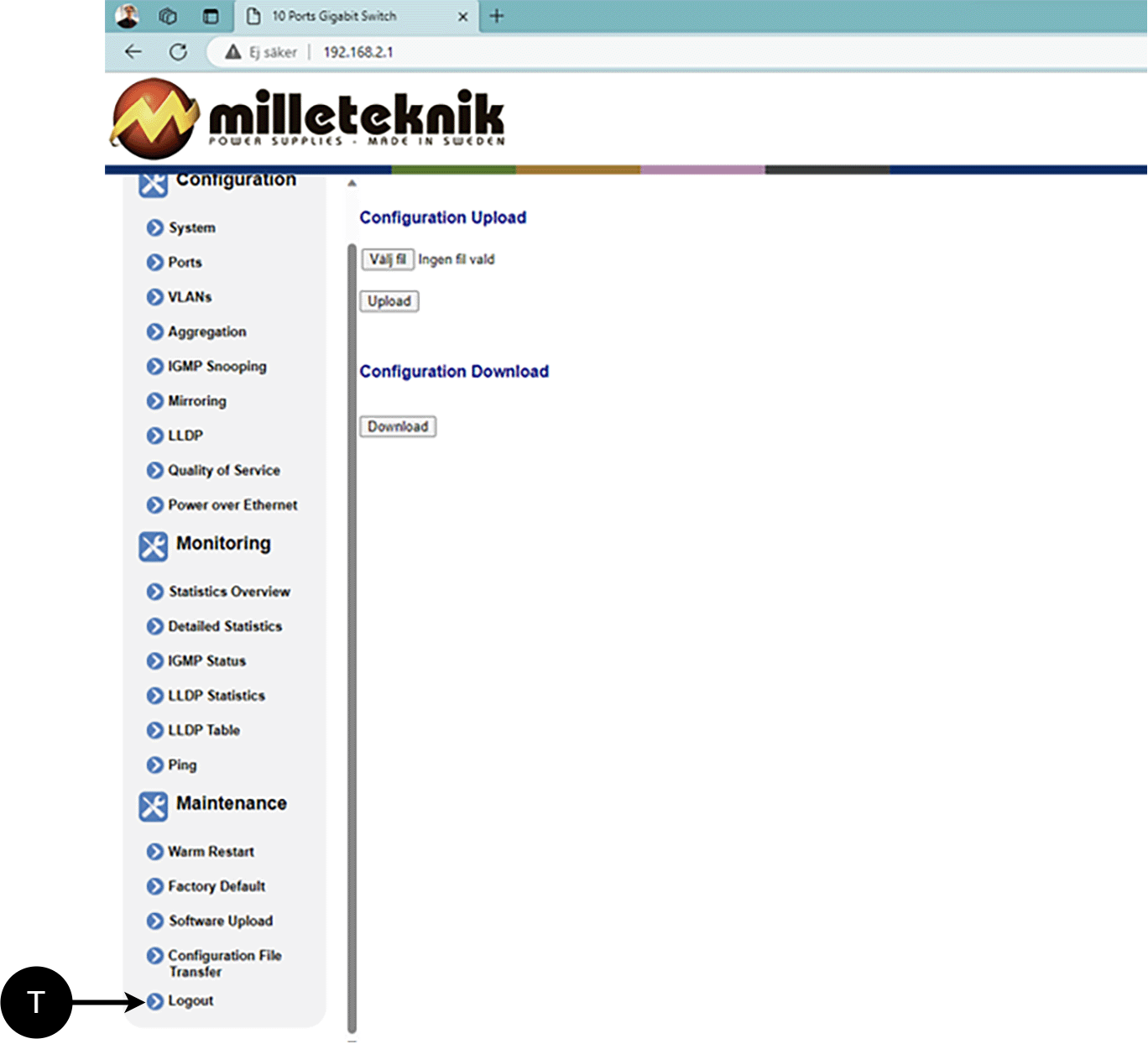
T: Log out of the switch. This does not affect the operation of the switch.
About this information
Specifications are subject to change without notice. Milleteknik accepts no liability for typographical errors. Information is updated without prior notice. |
Publication date 2026-09-21
Deployment - how to start the device
Danger
Personal injury or death can occur if the device is connected to the mains or live when disassembling / moving.
Connect load.
Connect mains voltage.
Plug in mains voltage.
Maintenance
The system with the exception of batteries is maintenance-free when installed in an indoor environment.
Safety Information - Service and Troubleshooting
If possible, disconnect the mains supply before starting any work, such as servicing, battery replacement, metering or troubleshooting.
Remove the battery fuse/plug before working on the DC side.
Check that all cables are properly connected and grounded before re-energizing the unit.
The product may contain components that become hot during operation. Avoid touching internal parts immediately after the power has been switched off.
If fuses blow repeatedly see Troubleshooting or disconnect the unit and contact Milleteknik technical support.
In case of suspicion of damage, liquid ingress or burnt odour, the product must not be used until it has been inspected by qualified personnel.
During operation, the housing should be closed and locked (if the device has a lock).
Only authorized service personnel may perform repairs on the device.
Use only original fuses and batteries of the same type and value as specified in the manual/product sheet.
Milleteknik is not responsible for damage caused by improper handling, modification or unapproved components.
Troubleshooting
If the device does not work as expected, go through the following checks:
Trouble | Possible cause | Action |
|---|---|---|
No voltage out. | No mains voltage, fuse triggered, or failure of batteries or battery deep discharge protection has entered. | Check the feed and fuses. |
LED flashes. | Information, warning or error. | See panel or manual for explanation. |
Fuses blown frequently. | Short circuit or overload. | Check connected devices, change the fuse only after the cause is fixed. |
The device gets hot. | High load or insufficient ventilation | Check that the rated current is not exceeded and that air flow is present around the housing. |
If the problem persists after these checks, contact Milleteknik support and provide the product name, serial number, and a brief description of the fault.
Tasks | Where can I find the task? |
|---|---|
Product designation | On the nameplate of the product. |
Serial Number | On the nameplate of the product. |
Error description. | Briefly describe what has happened and when the error occurs. |
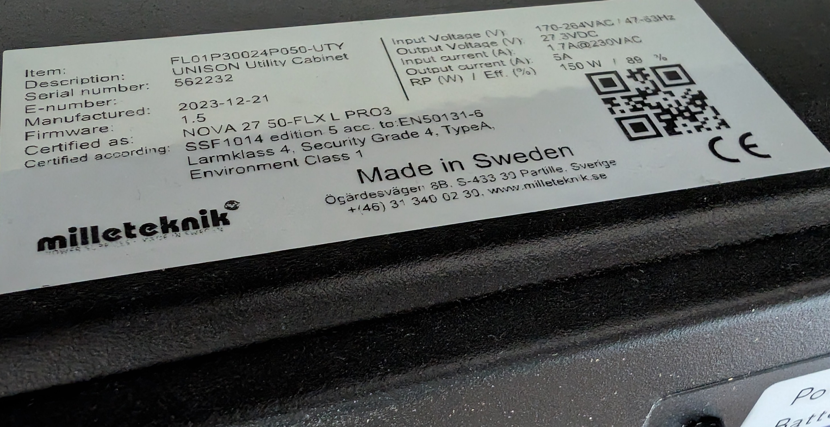
The nameplate is located on the device, usually on the outside. The placement may vary depending on the product
Contact path | Assignment |
|---|---|
Telephone | 031-340 02 30 |
Website |
Product sheet - power supply / battery backup
Product Sheet
PoE
Product Identification
Product designation | Part number | E-number (SE) |
|---|---|---|
PoE Switch 8p PS UT S | PL02P00048P050P-UTS | 51 73 418 |
Technical description
Power supply to power PoE devices such as surveillance cameras and other PoE powered devices.
PoE switch with eight PoE fed ports and two LAN ports and one sfp port. Power supplies power PoE cards. The device lacks batteries, so backup power in case of power failure is not possible
Quick Facts | |
|---|---|
Supply voltage (V) | 230V AC, +/- 10%, 47Hz- 63Hz |
Output voltage (V) | 54.6 V DC, (48 V DC) Batteries not possible to connect to the device. Also applicable in battery operation. |
Areas of application
Areas of application | Yes | No |
|---|---|---|
IP camera, power supply. | ✔ | |
Networked devices that can be powered by PoE. | ✔ |
Electrical data
Electrical data | |||||||||||||||||||||||||||||||||||||||||||||||||
|---|---|---|---|---|---|---|---|---|---|---|---|---|---|---|---|---|---|---|---|---|---|---|---|---|---|---|---|---|---|---|---|---|---|---|---|---|---|---|---|---|---|---|---|---|---|---|---|---|---|
Supply voltage | 230V AC, +/- 10%, 47Hz- 63Hz | ||||||||||||||||||||||||||||||||||||||||||||||||
Charge current | Depending on the power outlet. | ||||||||||||||||||||||||||||||||||||||||||||||||
Efficiency[a] | 93% | ||||||||||||||||||||||||||||||||||||||||||||||||
Standby consumption | 0.5W | ||||||||||||||||||||||||||||||||||||||||||||||||
Voltage out | 54.6 V DC, (48 V DC) Batteries not possible to connect to the device. Also applicable in battery operation. | ||||||||||||||||||||||||||||||||||||||||||||||||
Power (W) | 30.8W per port | ||||||||||||||||||||||||||||||||||||||||||||||||
[a] At rated load. | |||||||||||||||||||||||||||||||||||||||||||||||||
Load outputs
Load outputs | |
|---|---|
Number of loading outputs | PoE switch can drive load. Load output to power other applications |
POE outputs | |
|---|---|
Number of PoE ports (RJ-45) | 8 |
PoE budget | 240W |
PoE, power per port | 30,8 W |
Estimated input current to the PoE conversion at maximum load | Approx 9.02 A at 27.3 V DC |
Number of LAN ports | 2 |
Network ports/interfaces, RJ-45 | 100 Mbit/s 1000Mbps |
Managed | Yes |
Alarm and protection
Protection | Yes | No |
|---|---|---|
Overload Protection/Surge Protection | ✔ | |
Over-temperature protection | ✔ | |
Short circuit protection | ✔ |
Communication and Indications
Communication and Indications | Yes | No | Additional information. |
|---|---|---|---|
Communication to the parent system | ✘ | ||
Indications | ✘ |
|
Enclosure and Mechanics
Enclosure and Mechanics | |
|---|---|
Type | Universal enclosure for pole mounting |
IP class | IP65 |
Material | Polyester plastic |
Colour | Beige |
Cable grommets | ! 9 |
Lock | ✘ |
Fan in enclosure | ✘ |
Assembly, installation and qualification requirements
Mounting | Yes | No |
|---|---|---|
Pole. | ✔ |
Installation | Yes | No |
|---|---|---|
Fixed installation. | ✔ |
Dimensions, weight and packaging information
Net weight | Weight with packaging |
|---|---|
5.0 kg | 5.4 kg |
Packaging | |
|---|---|
Packaging | Cardboard and impact protection in cardboard |
Quantity in pack | 1 pc. |
Packaging Type (GS1 T0137) | BX box. |
Conditions EUR pallet | EUR pallets may not be stacked during transport or storage. Stacking may result in damage to product and packaging |
Transport environment | The product must be protected from condensation and direct precipitation during transportation. |
Transport temperature (without battery) | −30 °C to +70 °C |
Storage environment | Dry indoor environment, protected from condensation. Relative humidity: max 95%, non-condensing |
Storage temperature without batteries | −20 °C to +60 °C |
Fits
Contact
So when you reach us | |
|---|---|
Switchboard | 031-340 02 30 |
Technical support | support@milleteknik.se |
Sales | sales@milleteknik.se |
WWW | www.milleteknik.se |
Address | Ögärdesvägen 8B, 433 30 Partille |
About this information
Specifications are subject to change without notice. Milleteknik accepts no liability for typographical errors. Information is updated without prior notice. |
Publication date 2026-09-21
Compliance and regulatory compliance
Delivery time, warranty and terms
Delivery time, warranty and terms | |||||||||||||||||||||||||||||||||||||||||||||||||
|---|---|---|---|---|---|---|---|---|---|---|---|---|---|---|---|---|---|---|---|---|---|---|---|---|---|---|---|---|---|---|---|---|---|---|---|---|---|---|---|---|---|---|---|---|---|---|---|---|---|
Warranty period[a] | The product has a two (2) year warranty against manufacturing defects. In addition to the regular warranty period, an additional three (3) year warranty can be purchased. | ||||||||||||||||||||||||||||||||||||||||||||||||
Special warranty conditions | Components manufactured by manufacturers other than Milleteknik are not covered by Milleteknik's warranty.See also general terms and conditions. | ||||||||||||||||||||||||||||||||||||||||||||||||
General Terms and Conditions | ALEM09 with exceptions, see: www.milleteknik.se/conditions/ | ||||||||||||||||||||||||||||||||||||||||||||||||
Support | Telephone support and email support during the warranty period are free of charge. For spare parts that are not covered by warranty, there is a charge | ||||||||||||||||||||||||||||||||||||||||||||||||
Delivery and stock | |||||||||||||||||||||||||||||||||||||||||||||||||
Delivery time[b] | Or as per agreement. Delivery from factory, transportation time is added. | ||||||||||||||||||||||||||||||||||||||||||||||||
[a] If the device is purchased through a wholesaler or other supplier, other warranty conditions may apply. [b] In the case of larger orders, delivery time increases, acc. to agreement. | |||||||||||||||||||||||||||||||||||||||||||||||||
Operation and maintenance
Operation | Data | Additional information | |||||||||||||||||||||||||||||||||||||||||||||||
|---|---|---|---|---|---|---|---|---|---|---|---|---|---|---|---|---|---|---|---|---|---|---|---|---|---|---|---|---|---|---|---|---|---|---|---|---|---|---|---|---|---|---|---|---|---|---|---|---|---|
Environment | Outdoors, Grade 3. | ||||||||||||||||||||||||||||||||||||||||||||||||
Operating temperature (permissible) [a] | -25°C to +50°C | Class 3 according to EN 50131-6/ EN 60839-11 | |||||||||||||||||||||||||||||||||||||||||||||||
Load, power supply | 80% | Average load shall not exceed 80% of the rated capacity of the power supply. | |||||||||||||||||||||||||||||||||||||||||||||||
[a] Specifies the permissible ambient temperature range in which the product can operate without damage. See also table on battery life. | |||||||||||||||||||||||||||||||||||||||||||||||||
Yes | No | Interval | Additional information |
|---|---|---|---|
✔ | The product is maintenance-free |
Certifications and approvals
Complies with | Directives |
|---|---|
PoE | IEEE 802.3af, IEEE 802.3at/30.8 W. Note that 802.3at type2 is not supported, as the PoE card does not have a type 2 handshake function. |
Emissions | BS EN/EN55032 (CISPR32) Klasse B, BS EN/EN61000-3-2, -3, EAC TP TC 020, CNS13438, GB9254 Klasse B, GB17625.1A11:2020 (CISPR 32), Class B |
Immunity | EN61000-6-2:2005, EN61000-4-2, -3, 4, -5, -6, -11 SS-EN 50130-4:2011 Edition 2, EN50131-6 |
CE | CE marking according to Regulation (EC) No 765/2008 |
RoHS | RoHS Directive 2011/65/EU, including amendment (EU) 2015/863 |
EMC | EMC Directive 2014/30/EU |
Electrical safety (LVD) | Low Voltage Directive 2014/35/EU |
Environmental data
Environmental data | Y/N | Information | Additional information. | ||||||||||||||||||||||||||||||||||||||||||||||
|---|---|---|---|---|---|---|---|---|---|---|---|---|---|---|---|---|---|---|---|---|---|---|---|---|---|---|---|---|---|---|---|---|---|---|---|---|---|---|---|---|---|---|---|---|---|---|---|---|---|
Building Product Declaration (BPD) | ✔ | Yes, see iBvd at www.milleteknik.se. | - | ||||||||||||||||||||||||||||||||||||||||||||||
REACH Information Obligation (EC) No 1907/2006 | ✔ | Yes, see the DoC at www.milleteknik.se The product complies with REACH Regulation (EC) No 1907/2006. | If empty, the product is not covered. | ||||||||||||||||||||||||||||||||||||||||||||||
SVHC substances, CAS/EC | ✔ | Yes, lead, 7439-92-1/231-100-4 | For text, see iBvd at www.milleteknik.se. If blank, substance is missing. | ||||||||||||||||||||||||||||||||||||||||||||||
Subject to the RoHS Directive, (EU) 2015/863) | ✔ | Yes, see the DoC at www.milleteknik.se | |||||||||||||||||||||||||||||||||||||||||||||||
WEEE 2012/19/EU | ✔ | The product contains electrical components or wiring and is covered by the WEEE Directive (2012/19/EU). | If empty, the product is not covered. End-of-life products must be returned to a recycling centre | ||||||||||||||||||||||||||||||||||||||||||||||
Battery Regulation (EU) 2023/1542 | If empty, the product is not covered. | ||||||||||||||||||||||||||||||||||||||||||||||||
SCIP No 2008/98/EC | ✔ | Yes, registered under the EU Waste Directive where applicable, (2008/98/EC). | If empty, no SCIP number is needed. | ||||||||||||||||||||||||||||||||||||||||||||||
Conflict minerals (EU) 2017/821 | ✗/✗/✗/✗/✔ | No=Gold, Tungsten, Tantalum, Cobalt. Yes=Tin | Tin in solders in printed circuit boards purchased through a Swedish supplier. | ||||||||||||||||||||||||||||||||||||||||||||||
Contains nanomaterials: EC 1272/2008 | ✗ | The product does not contain nanomaterials. | |||||||||||||||||||||||||||||||||||||||||||||||
Ecodesign 2009/125/EC | Milleteknik's products are intended for professional use and are therefore not directly covered by the Ecodesign Regulation (EU 2019/1782). As some components may be covered, we nevertheless disclose relevant information[a], where applicable, to provide our customers with confidence in their choice. | ||||||||||||||||||||||||||||||||||||||||||||||||
Machine Directive 2006/42/EC | The product is part of electrical systems, is subject to the relevant electrical and safety directives and is not a machine according to the Machinery Directive (2006/42/EC). Will be replaced by Machinery Regulation (EU) 2023/1230, which will apply in 2027. | ||||||||||||||||||||||||||||||||||||||||||||||||
The product is designed for a long service life, which reduces the environmental impact. End-of-life products are handed over to the nearest recycling centre. | |||||||||||||||||||||||||||||||||||||||||||||||||
[a] Standby consumption and power. | |||||||||||||||||||||||||||||||||||||||||||||||||

Manufacturer and country of origin
Manufacturer[a] | Milleteknik AB | ||||||||||||||||||||||||||||||||||||||||||||||||
Customs tariff number | 85044095[b] | ||||||||||||||||||||||||||||||||||||||||||||||||
Country of origin | Sweden | ||||||||||||||||||||||||||||||||||||||||||||||||
[a] Manufacturer refers to the brand indicated on the product. In the event of a discrepancy between the marking of the product and this product sheet, the marking of the product shall apply [b] Verify with the Customs Ombud/Customs Service for export/import; alternative classification 85044055 may become applicable if the product is assessed as a battery charger. | |||||||||||||||||||||||||||||||||||||||||||||||||
Appendix
Eligibility requirements, installation
Eligibility requirements vary between countries. The table summarizes national requirements for fixed installation and connection of equipment with a plug socket, respectively.
Options on the secondary side of the product, such as 12 V, 24 V or 48 V DC, are connected according to the respective instructions. Work on the network connection of the product shall be carried out in accordance with national qualification requirements
Permission Requirements for Installation | Fixed installation (230 V) | Plug | Additional information |
|---|---|---|---|
Sweden | ✔ | ✗ | Fixed installation may be performed by technicians but shall be under the responsibility of a qualified installer. (Electrical Safety Act, SS 436 40 00) Plug may be connected without authorization. |
Norway | ✔ | ✔ | Requirements for qualified electricians also for equipment with a plug socket in fixed installations. (NEK 400, DSB |
Finland | ✔ | ✗ | Plug may be connected without authorization. (Tukes, SFS 6000 |
Denmark | ✔ | ✗ | Plug may be connected without authorization. (Safety Board |
Germany | ✔ | ✗ | All fixed installations require a qualified electrician according to VDE 0100. Plug sockets may be connected without authorization, but only by person with basic electrical knowledge (“Elektrotechnisch unterwiesene Person”) |
Miscellaneous
The difference between PoE, PoE+ and PoE++.
Reference table: environmental classes according to EN 50130-5 (referred to in EN 50131-6)
Class | Type | Temperature range |
|---|---|---|
Environmental Class 1 | Heated indoors (type office/residence). | +5°C to +40°C |
Environmental Class 2 | Generally indoors (type warehouses/stairwells, not temperature controlled). | -10°C to +40°C |
Environmental class 3 | Protected outdoors. | -25°C to +50°C |
Environmental class 4 | Generally outdoors. | -25°C to +60°C |
About this information
Specifications are subject to change without notice. Milleteknik accepts no liability for typographical errors. Information is updated without prior notice. |
Publication date 2026-09-21
[1] Translations in languages other than Swedish are indicative only and not verified. Translation should always be checked against the Swedish original to ensure accurate information