
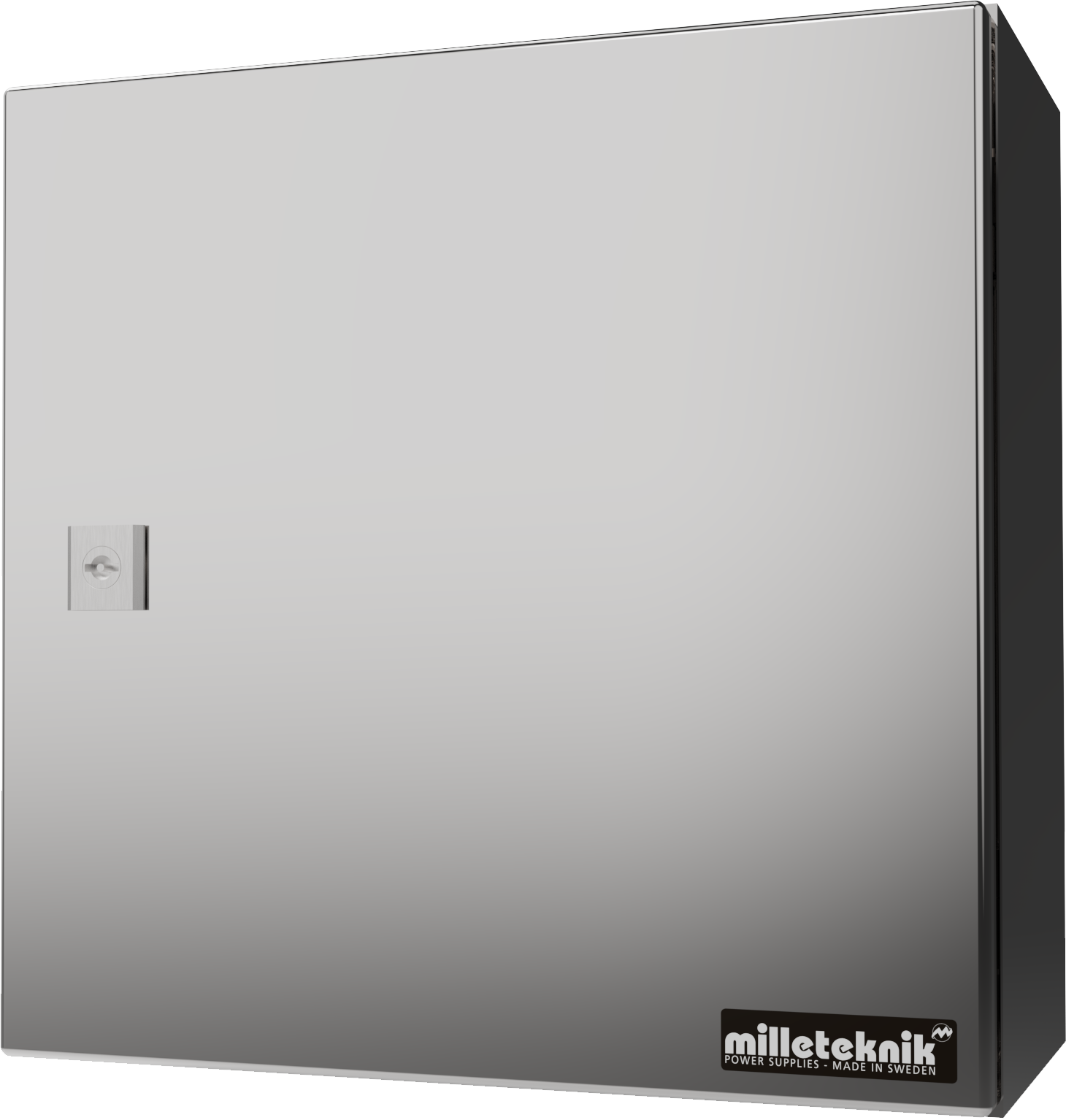
About this document
This document is subject to change without prior notice.
All information is published with reservation for printing errors.
Installation and commissioning
Instructions for installation and commissioning.
About NOVA 24V 5A OUT L
NOVA 24V 5A UT L is a power supply with battery backup for outdoor use.
Controlled charging function
Built to withstand Nordic conditions - summer and winter.
The product differs from indoor battery backups from Milleteknik and some functions have been added and others have been dropped.
Function | NOVA (with PRO3) | NOVA 24V 5A OUT L (with PRO3) | Comment |
|---|---|---|---|
Indication on cabinet door? | Yes | No | Indication of NOVA 24V 5A UT L is visible on the circuit board. |
Alarm over communication? | Yes | No | NOVA 24V 5A UT L is not prepared to communicate with superior systems. |
Expandable for longer reserve operating time? | Yes | No | NOVA 24V 5A UT L cannot be extended with battery boxes. |
Is it intended for installation and operation indoors? | Yes | No | NOVA can only be used indoors, class 1. |
Is it intended for installation and operation outdoors? | No | Yes | NOVA 24V 5A UT L has insulation and heating cable and housing for outdoor use. |
Component overviews
Component Overview Mounting Kits
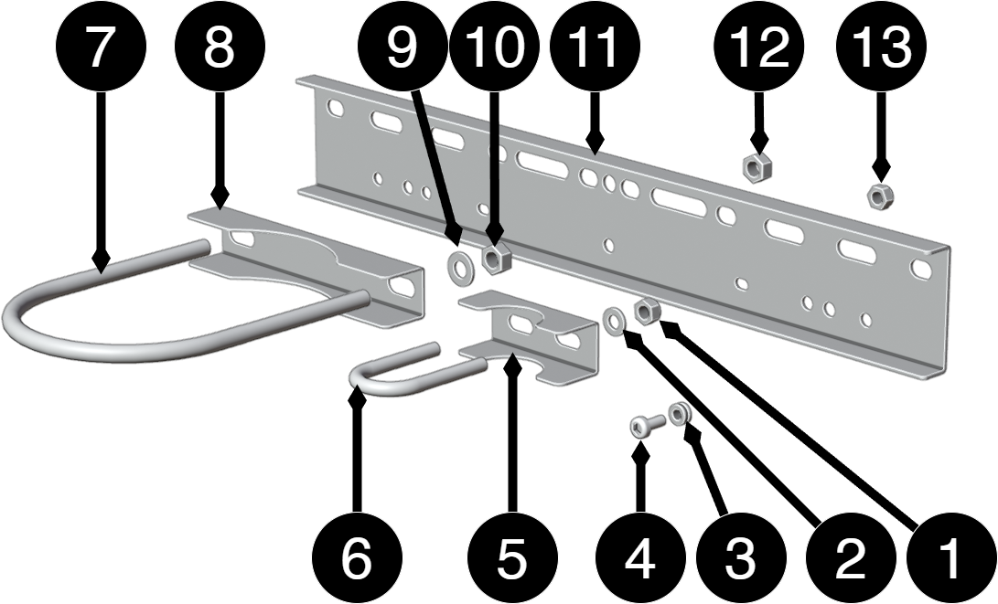
No. | Explanation | Size | Number |
|---|---|---|---|
1 | Fixing plate | M8 | 4 |
2 | U-bolt for mast | RBR M6x12 | 4 |
3 | U-bolt for pole | OD12 | 4 |
4 | Washers and nuts | M6x14 | 4 |
5 | Counter for smaller u-bolt | - | 2 |
6 | U-bolt, smaller | 28mm | 2 |
7 | U-bolt, larger | 125mm | 1 |
8 | Counter for larger u-bolt | - | 1 |
9 | Washer | 10 (5x20x2) | 4 |
10, 12,13 | Nut | M10 | 8 |
11 | Sheet rail for mounting in enclosure | - | 1 |
Component overviewNOVA FLX L
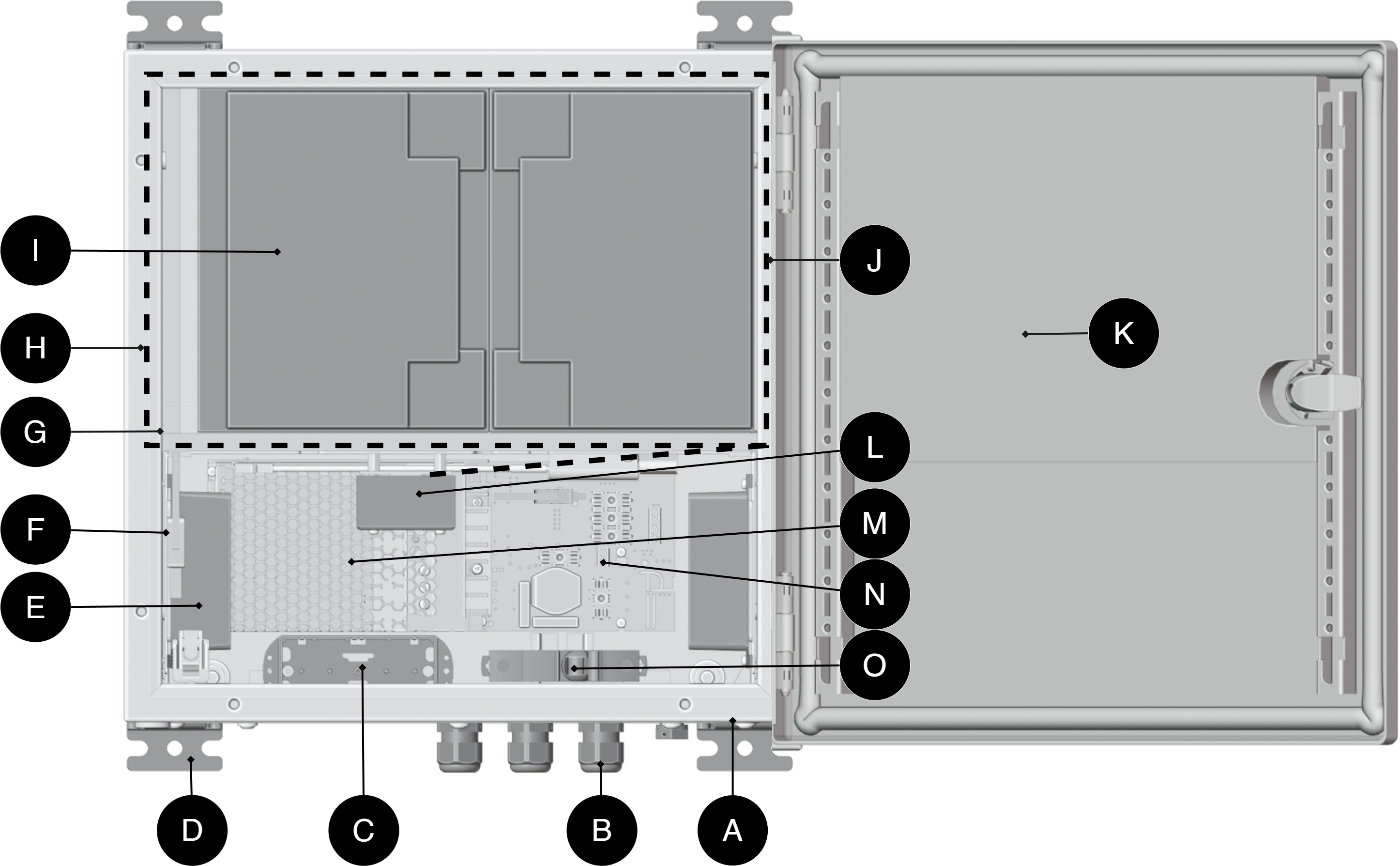
Number | Explanation |
|---|---|
B1 +, B2 + | Battery cable + |
B1 -, B2 - | Battery cable - |
C | Place for optional cards. |
D | Wall mount. |
E | Indicator diode |
F | The power supply, location and type vary with configuration. |
G, K | Motherboard |
H, J | Battery fuse |
I | Connection Load. If there are optional cards in the unit, the load must be connected there, see 8. |
J | Protection for temperature cable and battery. |
K | Heating cable. |
L | Lockable door. |
M | Power supply unit. |
N | Frost protection guard |
O | Fan. |
Notice
Fan should be cleaned regularly, at least every 12 months.
Enclosures
General assembly instructions
Outdoor mounting on pole
The product is intended for mounting on a pole with rails or corresponding fastening parts.
Enclosure to be mounted vertical.
For good ventilation, at least 100 mm of free space should be provided around the enclosure.
Use rails and fasteners that are compatible with the weight and mounting pattern of the product.
Install the rails in the product before installing the post brackets or pipe clamps.
Place pipe clamps or corresponding fastening parts around the post and connect them to the mounting points of the rails.
Check that the product is aligned and mounted in a vertical position before tightening.
The diameter and material of the post should be suitable for the selected type of fastening detail.
Tighten all screws and nuts according to the recommendations of the fastening details.
Ensure that the product is firmly fixed and cannot rotate or slide on the post after assembly.
Cable connections should be oriented downwards or according to the specific installation instructions of the product.
Avoid locations where water can flow directly onto the enclosure from surfaces above.
Avoid placement in direct sunlight or near heat sources.
Installation shall be carried out in accordance with the applicable installation rules and by a competent installer.
Mounting
Use the appropriate screw for mounting on a wall or in a 19" rack. Screws for mounting on a wall or in a rack are not included.
For wall mounting in concrete, concrete screws must be used. For rack mounting, M6 with basket nut is used
Screw length should be adjusted according to wall material and load. The specified screw length is the minimum allowable length
Mounting holes, spacing and ø.
Mounting options and accessories
To ensure a smooth installation, we offer several custom mounts for our UT series enclosures (S, M and L). In the matrix below you will see which options are compatible
Please note that a wall mount is always included as standard with all models. For pole mounting or needing extra sun protection, separate optional kits are required
Enclosure | Wall Bracket | Pole Bracket | Sun protection | Camera and pole mount (upcoming) | Speaker Bracket |
|---|---|---|---|---|---|
OUT L | Included | Pole Mount Kit for UT L | Sun Shield Kit | Not possible | Not Possible |
Accessories | Enclosure |
|---|---|
Pole Mount Kit for UT L | OUT L |
Sun Shield Kit | UT S, UT M and UT L |
Mounting on pole and mast
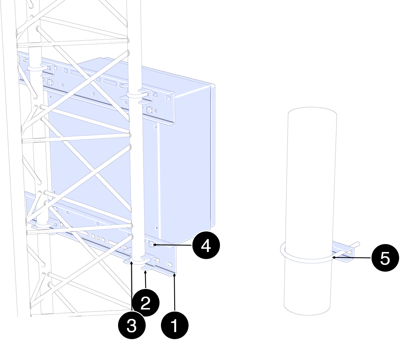
See component overview for screw, nut, washers and spacers.
No. | Explanation |
|---|---|
1 | Sheet metal rail. |
2 | Counter. |
3 | U-bolt for mast/pipe. |
4 | Screw/nut for mounting in housing. |
5 | U-bolt for pole. |
Mounting on mast
Position the mounting plates (1) against the vertical tubes of the mast at the height where the enclosure is to be mounted. The holes should be in line with the attachment points of the U-bolts
Pass the U-bolts (3) around the mast pipe (2) and through the holes in the mounting plates (4). Install washers and nuts but do not tighten finally
Center the housing towards the front of the mast by adjusting the position of the mounting plates (4) sideways until the housing is flush.
Tighten the nuts on all U-bolts in turn from top to bottom to ensure uniform loading across the mast tubes.
Check the attachment by lightly loading the housing sideways and forward/backward, and verify that all U-bolts are properly aligned against the mast tube.
Mounting on pole
Place the mounting plates (1) on the upper and lower attachment points of the enclosure and attach them lightly with the screws provided. Do not tighten finally yet.
Pass the lower U-bolt (2) around the post and through the holes in the lower mounting plate. Install washers and nuts. Tighten lightly.
Pass the upper U-bolt (3) around the post and through the holes in the upper mounting plate. Install washers and nuts (4)
Adjust the position of the enclosure so that it is in solder and centered toward the post.
Tighten all nuts in sequence: — lower U-bolt — upper U-bolt — screws to the mounting plates
Check the attachment by lightly loading the enclosure forward/backward to ensure stable mounting.
Batteries - placement and connection
Connecting batteries
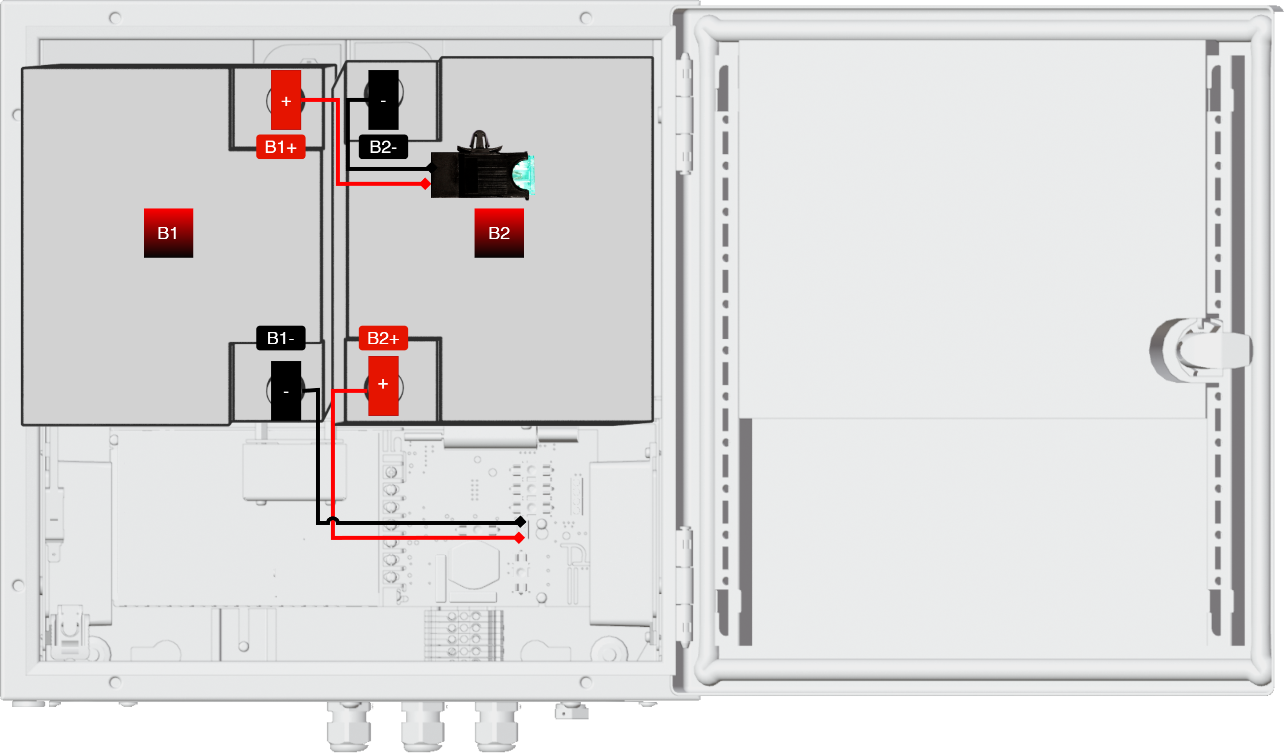
Note that configuration may differ by product.
Nr | Explanation |
|---|---|
B1 | Battery 1 |
B2 | Battery 2 |
B1+ | Plus terminal to battery fuse. |
B1- | Minus terminal to motherboard. |
B2- | Minus terminal to battery fuse. |
B2+ | Plus terminal to motherboard. |
Connection of power supply (230 V) and load
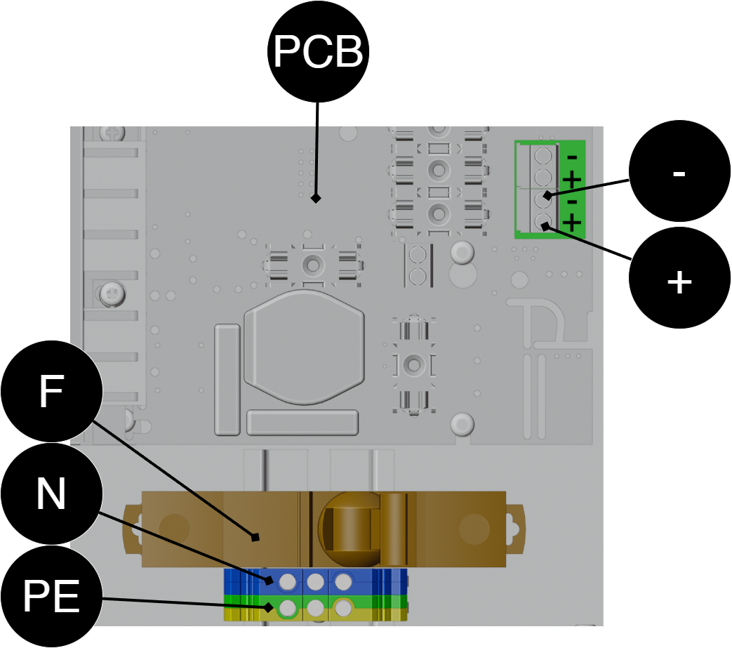
In the lower left corner is the connection for the mains and load.
Leave free air flow for fan, cable should lie against the floor of the unit.
Connect the load before connecting the mains.
Symbol | Explanation |
|---|---|
F | Phase. |
N | Zero. |
PE | Protective soil. |
+ | 24 V load +. |
- | 24 V load -. |
PCB | Motherboard, PRO3 - fuses are located here. |
Temperature cables - location
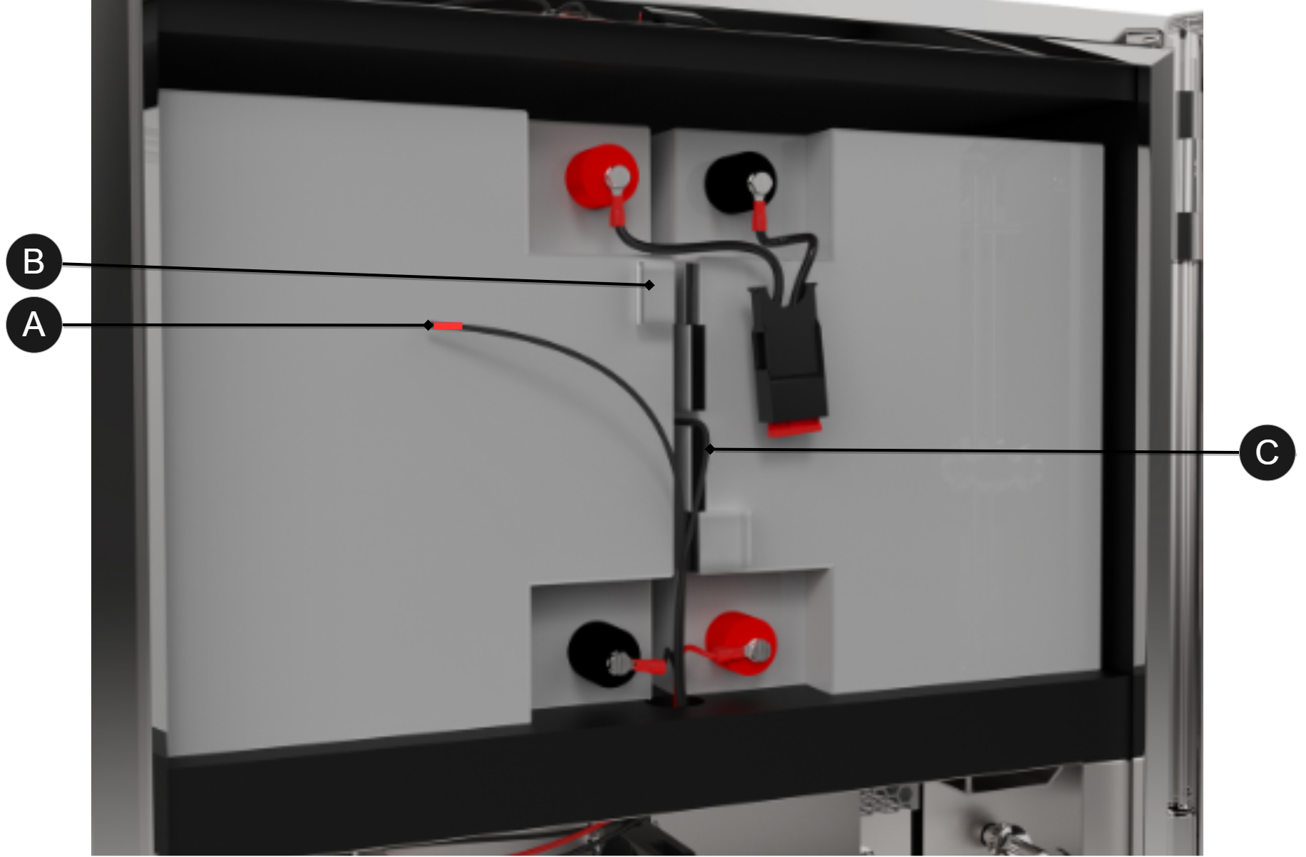
Letter | Explanation |
|---|---|
A | Temperature sensor should be placed between batteries, for antifreeze guard, (red at the top). |
B | Battery. |
C | Temperature cable between batteries, (black). |
Antifreeze guard
The device is equipped with antifreeze guard. When the temperature goes below +15°C, heating elements start to prevent loss of capacity or risk of batteries freezing
Heating elements start when the temperature in the enclosure falls below: | +15°C |
Commissioning - how to start the device
Connect batteries.
Switch on the battery fuse.
Connect load.
Connect mains voltage.
Connect mains voltage.
It can take up to 72 hours before batteries are fully charged.
Alarm displayed on cabinet door
In normal mode, the indicator LED shows a solid green light.
When operating system: If the indicator LED is off, deep discharge protection has been activated.
Notice
If the indicator light flashes every 15 seconds, the battery is fully charged and the charge is in rest phase to extend battery life. In the event of a power failure during the rest phase, the battery backup switches to battery operation as usual
Maintenance
The system, with the exception of fans and batteries, is maintenance-free. Check fans annually. Fan should rotate smoothly without any noise. Clean the fan from dust and dirt. The fan should be replaced if it does not rotate smoothly or is so dirty that it cannot be completely cleaned. If the fan does not work well, the air flow in the unit will be obstructed, as a result of which heat will increase in the housing, it will lead to the deterioration of battery life and thus the replacement interval of batteries will be significantly shortened
NOVA TERRA - Product sheet
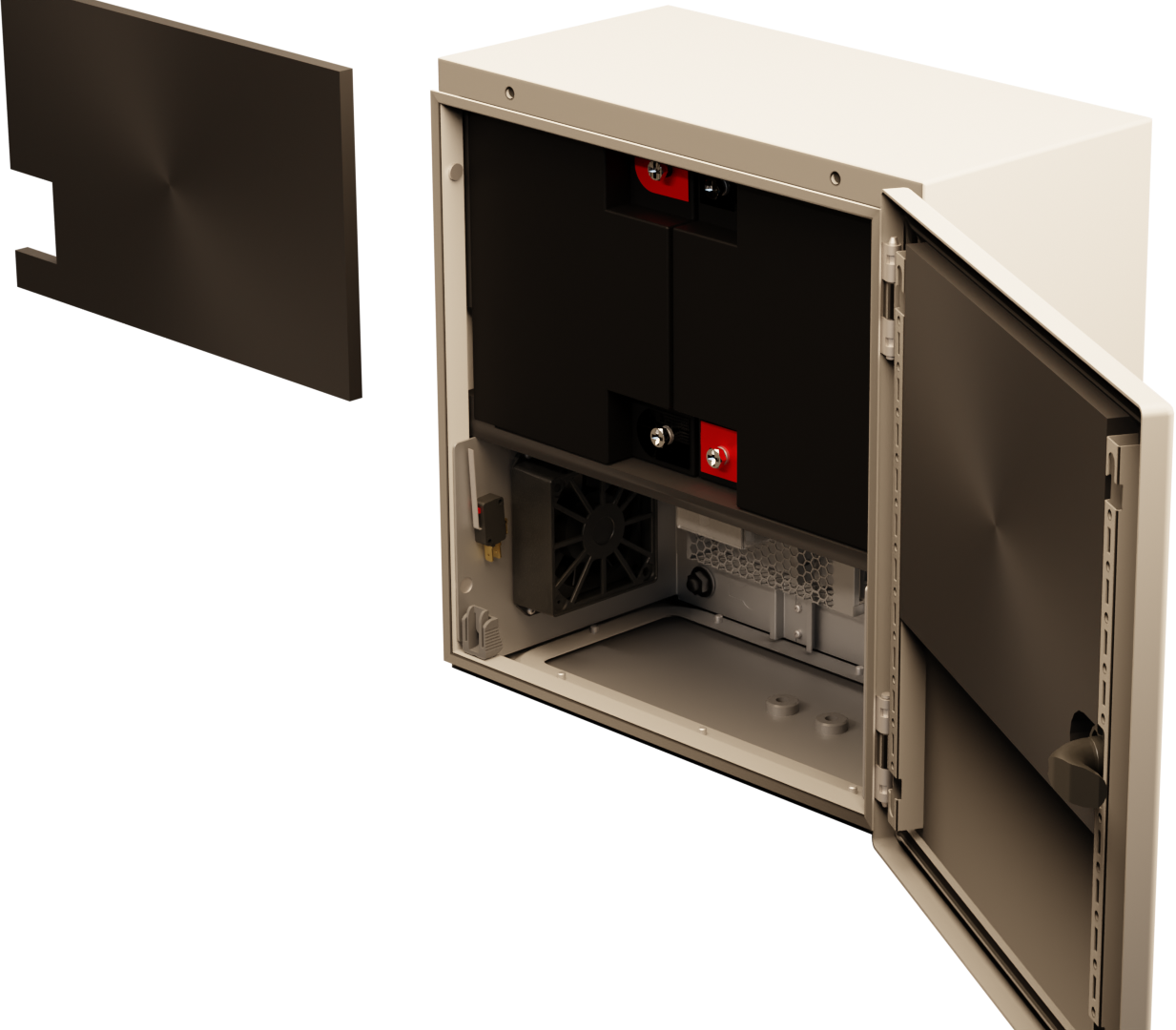
NOVA 24V 5A UT L - Power supply with battery backup
Product designation, article number and email number
Product designation | Item number | Email number | Certified according to |
|---|---|---|---|
NOVA 24V 5A OUT L | SA43P30024P050-UT01 | - | The product is not certified. |
About NOVA 24V 5A OUT L
NOVA 24V 5A UT L is a power supply with battery backup for outdoor use.
Controlled charging function
Built to withstand Nordic conditions - summer and winter.
The product differs from indoor battery backups from Milleteknik and some functions have been added and others have been dropped.
Function | NOVA (with PRO3) | NOVA 24V 5A OUT L (with PRO3) | Comment |
|---|---|---|---|
Indication on cabinet door? | Yes | No | Indication of NOVA 24V 5A UT L is visible on the circuit board. |
Alarm over communication? | Yes | No | NOVA 24V 5A UT L is not prepared to communicate with superior systems. |
Expandable for longer reserve operating time? | Yes | No | NOVA 24V 5A UT L cannot be extended with battery boxes. |
Is it intended for installation and operation indoors? | Yes | No | NOVA can only be used indoors, class 1. |
Is it intended for installation and operation outdoors? | No | Yes | NOVA 24V 5A UT L has insulation and heating cable and housing for outdoor use. |
Area of use
Power supply and backup power for surveillance, camera surveillance, access control systems and other outdoor applications.
Regulations and certifications
Requirements that the product meets
EMC: | EMC Directive 2014/30/EU |
CE marking: | Regulation (EC) No 765/2008 |
Emissions: | EN61000-6-:2001 EN 55022:1998: -A 1:2000, A 2:2003 Class B, EN61000-3-2:2001, EN 55032 (replaces EN 55022) |
Machinery Directive | The product is part of electrical systems, is subject to the relevant electrical and safety directives and is not a machine according to the Machinery Directive (2006/42/EC). |
Ecodesign | Milleteknik's products are intended for professional use and are therefore not directly covered by the Ecodesign Regulation (EU 2019/1782). As some components may be covered, we nevertheless disclose relevant information to give our customers confidence in their choice |


Circuit boards - Technical data
Technical data, motherboard: PRO 3
Info | Explanation |
|---|---|
Short name: | PRO 3 |
Product description | Motherboard in battery backup with advanced functions and communication to parent system. |
Own consumption, with relay card | Less than 100 mA. All relays retracted on external alarm card in normal mode. |
Switching time from mains voltage to battery operation | When batteries are idle: <5 microseconds. When batteries are in charge cycle: 0 (none). Batteries rest for 20-day cycles, after which a charging cycle picks up and charges the batteries for 72 hours. If there is a power failure when batteries are in the charge cycle, there is no switching time. |
Incoming electricity network | 230 V AC -240 V AC, 47-63 Hz. |
Fuse on mains | See table: Fuses. |
Indication | Indicator diode on circuit board / cabinet door |
Alarm
Alarm displayed on indicator LED on the front of the cabinet.
Cell fault in battery or unconnected battery.
Charger fault, undervoltage.
Charger fault, overvoltage.
Low system voltage, system voltage below 24.0 V in mains operation.
Low battery voltage, below 24.0 V DC in case of mains failure.
Power failure alarm.
Sabotage switch.
Fuse fault.
Aged battery
Expanding alarm functions are available via communication or with alarm cards.
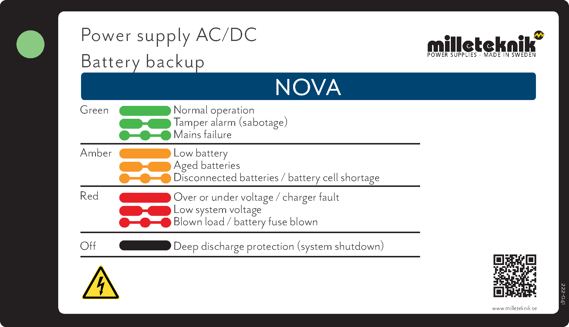
The picture is a guide to how alarms are displayed on the indication diode on printed circuit boards. It is not certain that allar alarms are present in the configuration of
Fuses | Type |
|---|---|
5 A | T5A |
Mains fuse for 24 V units up to 15 A | T2.5AH250V. Ceramic. |
Info | Explanation |
|---|---|
Deep discharge protection (Yes / No) | Yes. 12 V units protection at 10V, +/- 0.5 V. 24 V units protection at 20, +/- 0.5 V. |
Surge protection (Yes / No) | Yes |
Overtemperature protection (Yes / No) | Yes |
Short circuit protected = (Yes / No) | Yes |
Motherboard - description
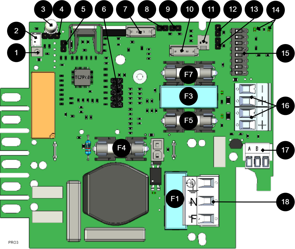
The motherboard controls the device and distributes power. See technical data for more information.
No . | On circuit board | Explanation |
|---|---|---|
1 | J24 | Power supply control. |
2 | J5 | 1=not prioritized 2=external alarm. |
3 | D9 | LED. |
4 | JU1 | For external LED in door. |
5 | J11 | Reset jumper, used when changing batteries. |
6 | JU6 | Connection for relay card or communication card or for updating firmware. Only one card or contact at a time can fit. |
7 | J29 | Connection to fan. |
8 | J101 | Connection to tamper contact. |
9 | J17 | Connection to tamper switch from battery box. |
10 | J35 | Not used. |
11 | J14 | Alarm input from external battery fuse, from battery box. |
12 and 13 | J10 and J100 | Alarm from external option card. |
14 | D18, D19 | LEDs show the status of communication (RS-485). |
15 | S3 | Dip switch |
16 | P2:1-4 | Load outputs |
17 | P3:1-3 | Connection communication. Not available. |
18 | P1:1-3 | Connection to the mains. |
Fuses
Fuse | Type | Explanation |
|---|---|---|
F1 | T2.5A | Mains fuse |
F3 | T16A | Load fuse 1 - (for P2:2) |
F4 | T16A | Battery fuse |
F5 | Load fuse 1+ (for P2: 1) | |
F7 |
| Load fuse 2 + (for P2:3) |
Warning for replacing fuses (current strength, A)
There is a risk of damage if the fuse is changed to a larger one than what the unit is delivered with. The function of the fuse is to protect the connected load and cables against damage and fire. It is not possible to change the fuse to a larger one to increase the power output.
Note on start-up with short-circuited batteries
Peak current at start-up with short-circuited batteries: Up to 30 A p-p for 200 ms. Always follow the start-up procedure.
Power supply
Power supply - Technical Data LRS-150-24
In: |
|---|
NOVA TERRA 24V 5A UT01 |
Info | Explanation |
|---|---|
Output voltage | 27.3 V |
Output current: | 0 A - 6.5 A |
Output voltage, ripple | 200 mVp-p |
Overvoltage | 28.8 V - 33.6 V |
Voltage recharge, ripple / current limitation | Less than 0.6 Vp-p |
Efficiency | 89% |
Current limitation | 110% - 140% |
Constant voltage | +/- 0.5% |
Regulatory accuracy | + / - 1.0% |
Input current (230 V) | 1,7 A |
Mains voltage frequency | 47 Hz- 63 Hz |
Mains voltage | 230 V AC - 240 V AC |
Brand effect | 156 W |
Temperature range | -30°C - +70°C |
Humidity range | 20% - 90% RH non-condensed |
Technical data enclosures
Enclosure
Technical data | |
|---|---|
Product description | AX Compact device cabinet, BHD: 380x380x210 mm, stainless steel plate, with mounting plate, with a door, a swivel lock. |
Article number: | AX 1380,000 |
Material | Cabinet: Stainless steel plate. Door: Stainless steel sheet. Ambient foamed PU seal. |
Color | Stainless steel |
Enclosure class NEMA | NEMA 1, 3R, 4, 12 |
Enclosure class IP according to EN 60 529 | IP 66 |
Type classification corresponding to UL 50E | Type 1, 3R, 4, 12 |
IK code | IK10 |
Dimension | Width: 380 mm, height: 380 mm, depth: 210 mm. |
Lock | Version for lock: Swivel lock: 1. Lock insert: 3 mm double lock. |
Weight / pack | 9.48 kg |
More technical data for enclosure can be downloaded from the manufacturer's website
www.rittal.com
Compact cabinet AX 380x380x210
E-number: 25 039 11
Warranty, support, country of manufacture and country of origin
Warranty
The product has a two-year warranty, from the date of purchase (unless otherwise agreed). Support during the warranty period can be reached at support@milleteknik.se or telephone, +46 31-34 00 230. Compensation for travel and / or working hours in connection with locating faults, installing repaired or replaced goods is not included in the warranty. Contact Milleteknik for more information. Milleteknik provides support during the product's lifetime, however, no later than 10 years after the date of purchase. Switching to an equivalent product may occur if Milleteknik deems that repair is not possible. Support costs may (at Milleteknik's discretion) occour after the warranty period has expired.
Manufacturer support
Manufacturers provide support for the life of the product, however, for a maximum of 10 years after the date of purchase. Switching to an equivalent product may occur if the manufacturer deems that repair is not possible. Support costs will be added after the warranty period has expired.
Support
Do you need help with installation or connection?
You will find answers to many questions at: www.milleteknik.se/support
Phone: +46 31-340 02 30
Support is open: Monday-Thursday 08:00-16:00, Fridays 08:00-15:00. Closed 11:30-13:15.
Spare parts
Contacted support for questions about spare parts.
Support after the warranty period
Milleteknik provides support during the life of the product, but no longer than 10 years after the date of purchase. Replacement for an equivalent product may occur if the manufacturer deems that repair is not possible. Costs for support and replacement are added after the warranty period has expired.
Questions about product performance?
Contact sales: 46 31-340 02 30, e-mail: sales@milleteknik.se
Contact us
Milleteknik AB
Ögärdesvägen 8 B
S-433 30 Partille
Sweden
+46 31-34 00 230
www.milleteknik.se
Country of manufacture
Country of manufacture / country of origin is Sweden. For more information, contact your seller.
Designed and produced by: Milleteknik AB
Designed and produced by Milleteknik AB
Product life cycle, environmental impact and recycling
The product is designed and constructed for a long service life, which reduces the environmental impact. The product's service life depends on, among other things, environmental factors, mainly ambient temperature, unforeseen load on components such as lightning strikes, external damage, handling errors, and more. Products are recycled by being handed over to the nearest recycling station or sent back to the manufacturer. Contact your distributor for more information. Costs that arise in connection with recycling are not reimbursed.

Batteries - recommended, not included
45 Ah, 12 V AGM battery
Fits in | Number of batteries |
|---|---|
NOVA 24V 5A OUT L | 2 |
Battery type | Excitement | Ah |
|---|---|---|
Maintenance-free AGM, lead-acid battery. | 12 V | 45 Ah |
Article number | E-number | Article name | Terminal | Measure. Height width depth | Weight per piece | Make |
|---|---|---|---|---|---|---|
MT113-12V45-01 | 5230546 | UPLUS 12V 45Ah 10+ Design Life battery | M5 Bult | 197x165x170 mm | 14.5 kg | UPLUS |
Address and contact details
Milleteknik AB |
Ögärdesvägen 8 B |
S-433 30 Partille |
+46 31 340 02 30 |
www.milleteknik.com |