
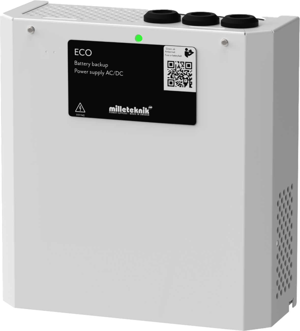
About
The ECO series are reliable and small battery backups for use with access systems, locking systems and other loads. The battery backups have controlled charging* which prevents batteries from overcharging, which significantly prolongs their service life.
Notice
This unit should be installed on a wall or in a 19" rack, indoors.
The temperature must be 15 - 30 ° C.
Mains voltage must be disconnected during installation.
Only authorized persons should install and maintain the unit.
Installation video

Product Identification
Product designation | Article number | E-number (SE) |
|---|---|---|
ECO 12V 5A S | SM01C10112P050 | 52 136 50 |
Revisions and the edition of this document
The current and most recently published edition of this document is available at www.milleteknik.com.
The validity of this document can not be guaranteed, as new editions are published without prior notice.
Original instructions for use: Swedish.[1].
Instructions for use, technical data and translations thereof may contain errors. It is always the responsibility of the installer to install the product in a safe manner.
Symbols
Symbols | Name | Explanation |
|---|---|---|
 | Warning | Risk of electric shock, improper installation or hot surfaces. Appears in some manuals |
 | Note | Used for supplementary information that clarifies the text. |
 | Caution/Important | Indicates the risk of equipment damage or malfunction. Also used for information that is important but not security-related |
 | Tips | Displays practical advice or shortcuts for installation, operation, or service. |
 | CE marking | The product complies with applicable EU directives and harmonised standards. |
 | Read the manual | Please read manual before installation and service. |
 | Do not dispose of in household waste | The product is covered by the WEEE Directive and must not be disposed of with household waste, it must be recycled and delivered to a recycling centre. |
 | Recycling | Packaging, products and other materials that do not contain electronics must be recycled in accordance with local environmental regulations. |
Component overviews
Component overview ECO 12V 10A M, ECO 24V 5A M, ECO 24V 10A M
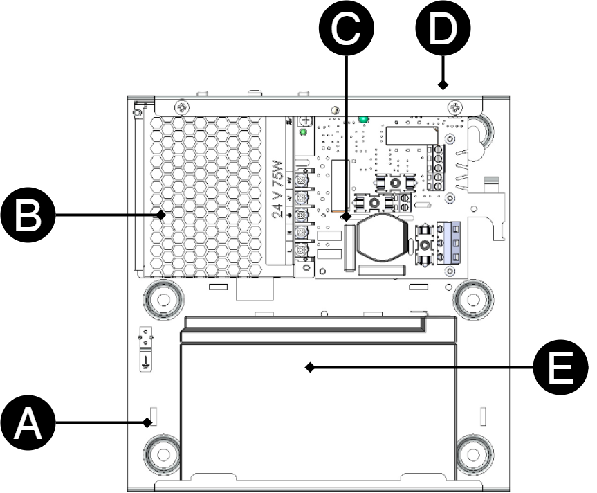
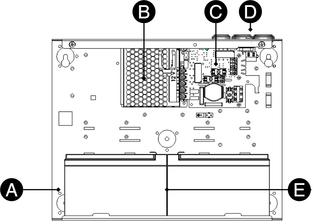
Left: ECO S. Right ECO M.
Number | Explanation |
|---|---|
A | Cabinet in powder-coated sheet metal. |
B | The power supply, location and type vary with configuration. |
C | Motherboard. |
D | Cable entries. |
E | Space for batteries. |
Enclosures
General assembly instructions
Mounting - wall mounting
Enclosure must be mounted vertically.
For good ventilation, at least 100 mm of free space should be provided above and on the sides of the enclosure. Do not block the flow of air on the sides
The device should be mounted at a comfortable working height, normally between 1.4 and 1.8 m.
Recommended distance between screw head and wall should be 1.5-2 mm.
Avoid placement in direct sunlight, near heat sources, or in environments with high humidity or dust.
Installation shall be carried out in accordance with the applicable installation rules and by a competent installer.
Batteries - placement and connection
Connection of battery ECO S 12 V
Caution
Check battery voltage before switching on. Before installation, the voltage of each individual battery must be measured. Never connect two batteries if their terminal voltage differs by more than 0.3 V (max 0.4 V). Too large a voltage difference may indicate a damaged battery and lead to performance degradation, battery damage or overheating with the risk of fire.
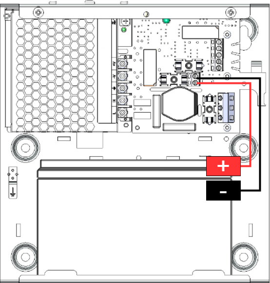
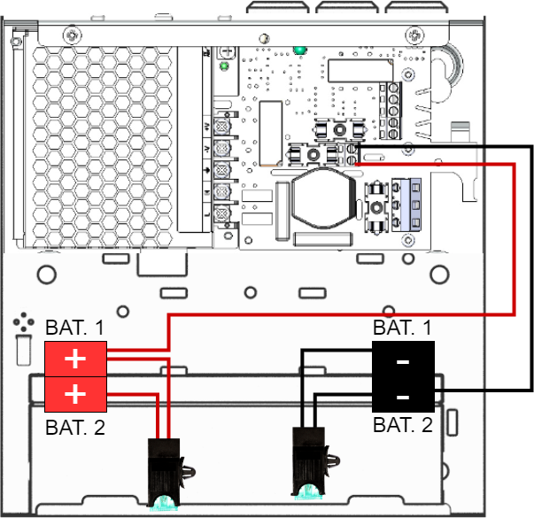
Left ECO 12V with 1 battery. Right ECO 12 V with two batteries.
12 V with a battery: Battery cables from motherboard are connected to battery plus and minus pole. Battery fuse is on circuit board.
12 V with two batteries: Battery cables from motherboard are connected to battery plus and minus pole of each battery. Fuses must be connected to each battery pole. A fuse on minus poles and a fuse on plus poles.
Note
Fuses that come with the device in a bag should not be used when using 1 battery.
Connection of batteries, 24V
Caution
Check battery voltage before switching on. Before installation, the voltage of each individual battery must be measured. Never connect two batteries if their terminal voltage differs by more than 0.3 V (max 0.4 V). Too large a voltage difference may indicate a damaged battery and lead to performance degradation, battery damage or overheating with the risk of fire.
Mains voltage should be disconnected when connecting batteries
Slide the batteries in from the side with the terminals facing each other (toward the center). Only use new batteries during installation and battery replacement.
Connect fuses on batteries. Connect red cable to + (plus) and black cable to - (minus)
Connect cables from battery backup to batteries. Connect red cable to + (plus) and black cable to - (minus)
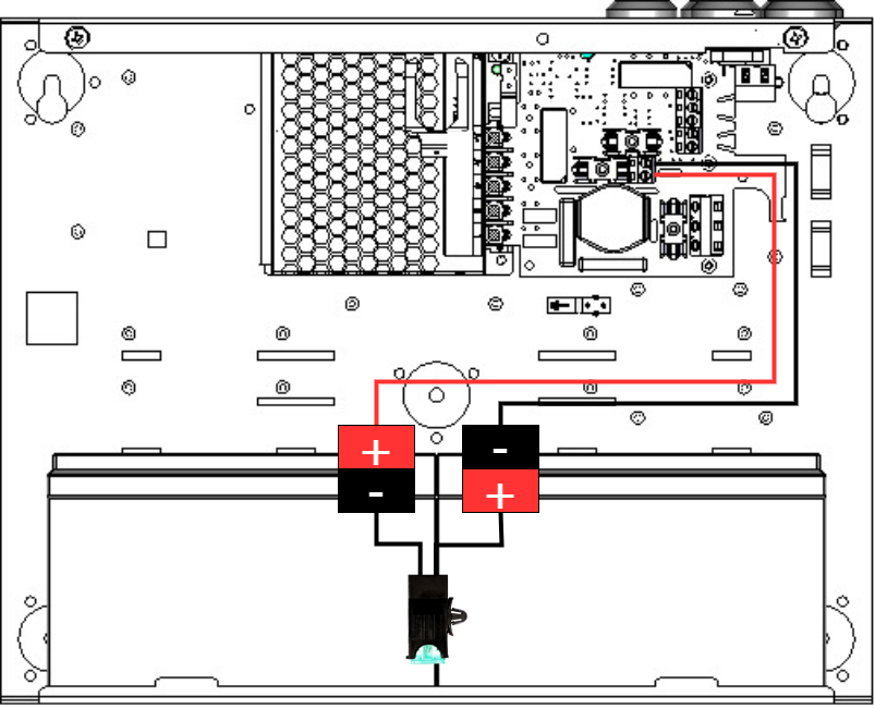
The picture shows how cables should be connected.
CEO3 v5 Up
Motherboard description
The card has several connections, below they are described those that are needed to connect the device.
Connect in this order
To minimize the risk of short-circuit errors, connect the components to the motherboard in the following order.
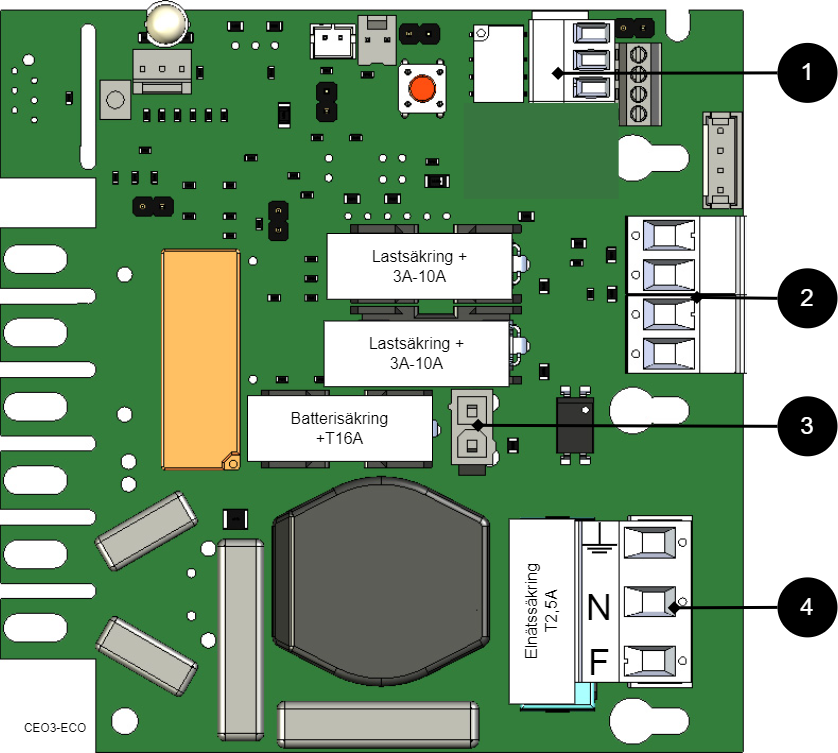
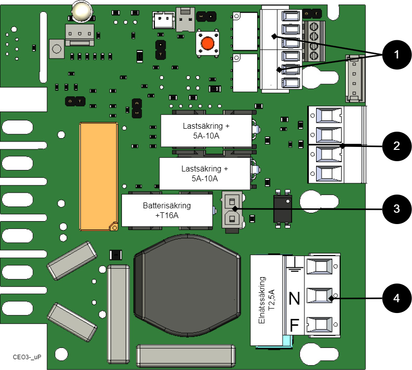
Nr | Explanation |
|---|---|
1 | Connect alarm. |
2 | Connect load. |
3 | Connect batteries |
4 | Connect mains. |
Connect alarm
Connect alarm on terminal P3.
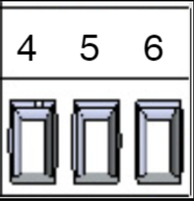
P3: 4-6 | Explanation |
|---|---|
Sum-alarm | |
P3: 4 | NC |
P3: 5 | Com |
P3: 6 | NO |
Connect load
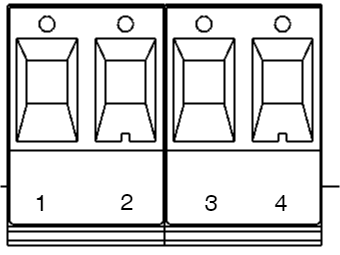
Circuit board number | Explanation |
|---|---|
P2: 1 | Connection for load 1 + |
P2: 2 | Connection for load 1 - |
P2: 3 | Connection for load 2 +. |
P2: 4 | Connection for load 2 -. |
Max current
The maximum current must not be exceeded. Max current is indicated on the rating plate on the device.
Danger
Mains voltage must be disconnected when working with stripped cables. It is the installer's responsibility to ensure that the correct skills are available for connecting 230 V to the unit. Maximum cable area is 4 mm2
Connect mains
Before connecting, the supply circuit should be disconnected and voltage-free. Verify that the conductor area and cable type meet the applicable installation rules and that the strain relief and insulation levels comply with the requirements for 230 V AC
After connection, all screw connections should be checked and tightened. Tensioning shall only take place after mechanical protection, caps and housing have been reassembled and comply with the contact protection according to EN 62368-1
Secure F and N with cable ties.
Important
Protective earth (PE) must be connected to the PE terminal on the motherboard. The motherboard is grounded via its mounting points in the enclosure, ensuring proper potential equalization between PCB and enclosure. Also the cover is grounded through ground cable/earth braid between cover and enclosure to maintain continuity and EMC
Mains wiring must be kept separate from other wiring to avoid EMC interference.
The protective earth (PE) must be connected to the PE terminal on the motherboard. The motherboard is grounded via its mounting points in the enclosure, ensuring correct equipotential bonding between the circuit board and the enclosure. The cover is also grounded via a grounding cable / grounding braid between the cover and the enclosure to maintain continuity and EMC function.
Check that the marking on the circuit board matches the wiring order on the terminal block.
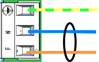
Connect the mains cable to the terminal block before it is re-inserted into the motherboard. Secure L (F in picture) and N with cable ties for electrical safety.
Letter | Explanation |
|---|---|
L | Fas |
N | Neutral |
PE |
Control alarm limit
Alarm for low battery voltage in battery operation can be controlled.
Fuses
Unit | Fuse | Type | Explanation |
|---|---|---|---|
All units | F1 | T2,5A | Mains fuse |
ECO 12V 5A S. | F2, F6 | T5A | Load fuse + |
All units | F7 | T16A | Battery fuse |
Warning for replacing fuses (current strength, A)
There is a risk of damage if the fuse is changed to a larger one than what the unit is delivered with. The function of the fuse is to protect the connected load and cables against damage and fire. It is not possible to change the fuse to a larger one to increase the power output.
Alarm displayed on cabinet door
In normal mode, the indicator LED shows a solid green light.
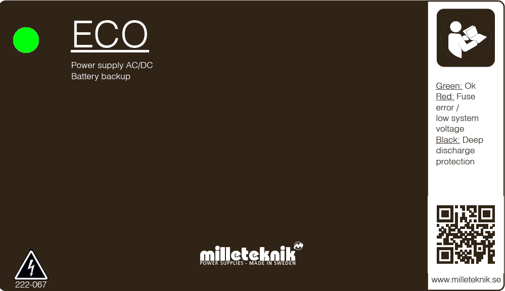 |
The display LED shows | Explanation |
|---|---|
Solid green light | Normal operation. |
Solid red light | Undervoltage, LED is green in the event of a power failure until the battery voltage drops below the alarm limit. |
When operating system: If the indicator LED is off, deep discharge protection has come into force.
ECO product sheet
Product sheet / technical data
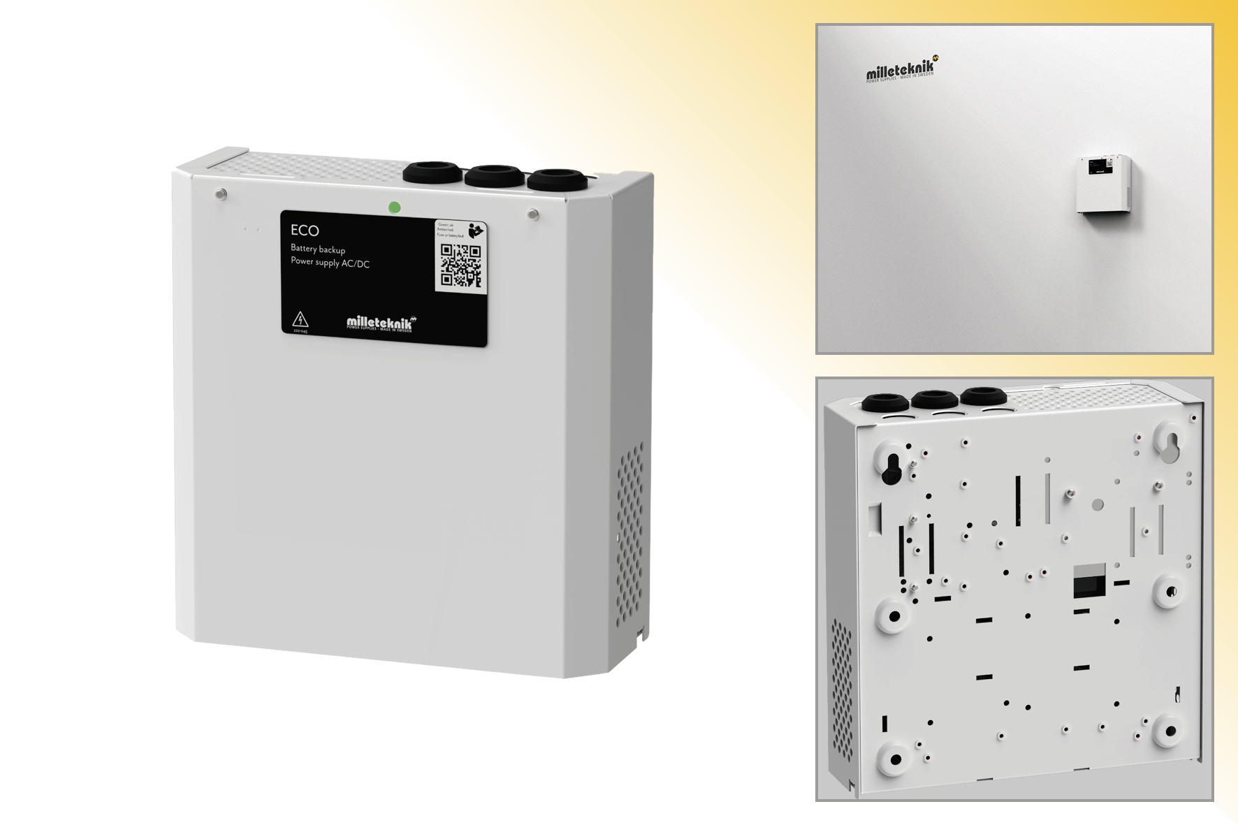
ECO S The unit must be wall-mounted.
Technical specifications
These technical specifications are subject to change without notice.
Product Identification
Product designation | Article number | E-number (SE) |
|---|---|---|
ECO 12V 5A S | SM01C10112P050 | 52 136 50 |
About
The ECO series are reliable and small battery backups for use with access systems, locking systems and other loads. The battery backups have controlled charging* which prevents batteries from overcharging, which significantly prolongs their service life.
Areas of use
Most used in:
Alarm
The device alarms for:
Undervoltage/low battery voltage.
Fixed installation
The product is intended for fixed installation. The battery backup must be installed by a qualified installer.
Test before installation of 230 V
"Cold start" means that the battery backup can be commissioned with only the batteries connected without the battery backup being connected to 230 V. This is practical if the installer is not a qualified electrician but still wants to be able to test the system.
Regulations and certifications
Requirements that the product meets
EMC: | EMC Directive 2014/30/EU |
Electricity: | Low Voltage Directive 2014/35/EU |
CE marking: | Regulation (EC) No 765/2008 |
Machinery Directive | The product is part of electrical systems, is subject to the relevant electrical and safety directives and is not a machine according to the Machinery Directive (2006/42/EC). |
Ecodesign | Milleteknik's products are intended for professional use and are therefore not directly covered by the Ecodesign Regulation (EU 2019/1782). As some components may be covered, we nevertheless disclose relevant information to give our customers confidence in their choice |

Expected operating time in the event of a power failure ( with new batteries)
System voltage | Number of batteries | Battery type | Load: 0.1 A | Load: 0.3 A | Load: 0.6 A | Load: 1 A | Load: 1.5 A | Load: 2 A |
|---|---|---|---|---|---|---|---|---|
12 V | 1 psc | 2.3 Ah | 12 h | 4 min | 2 h | 1 h | 40 min | 20 min |
12 V | 1 pcs | 7.2 Ah | 42 h | 19 h | 10 h | 5 h | 3 h | 2 h |
Circuit boards - Technical data
Technical data: CEO 3
Info | Explanation |
|---|---|
Article name | CEO3-ECO |
Product description | CEO 3 is the next generation circuit board for simpler battery backups. Advanced functions that were not previously possible in simpler battery backups are now available as standard. CEO 3 is manufactured with fewer components than before, which reduces the environmental impact. |
Measure | 120 x 55 mm x 52 mm |
Own consumption | 50 mA |
Fuses | See table: Fuses. |
Outputs | Output: two load outputs. |
Insurance | Load output: + secured. |
Max load | Maximum load is 10 A per load output (T2A is mounted from the factory) and the card's total load must not exceed 16 A. |
Alarm outputs | Alarm outputs: Sum alarm in case of fuse fault, see indication below. Alarm on potential-free relay contact. |
Alarm | Undervoltage, lights up red in the event of a power failure until the battery voltage drops below the alarm limit. |
Alarm via | Triggered load securing, potential-free shifting, CO / NO. |
Indication | Display showing operating status, alarms and faults. Operating indication: one indication diode per load output +/-. Solid green light = normal operation. |
Control alarm limit with JU2
Control alarm limit
Alarm for low battery voltage in battery operation can be controlled.
Fuses
Unit | Fuse | Type | Explanation |
|---|---|---|---|
All units | F1 | T2,5A | Mains fuse |
ECO 12V 5A S. | F2, F6 | T5A | Load fuse + |
All units | F7 | T16A | Battery fuse |
Warning for replacing fuses (current strength, A)
There is a risk of damage if the fuse is changed to a larger one than what the unit is delivered with. The function of the fuse is to protect the connected load and cables against damage and fire. It is not possible to change the fuse to a larger one to increase the power output.
Power supply
Power supply - Technical Data LRS-75-12
In: |
|---|
ECO 12V 5A S |
Info | Explanation |
|---|---|
Output voltage | 13.6 V |
Output current | 0 A - 6 A |
Output voltage, ripple | 120 mVp-p |
Overvoltage | 13.8 V - 16.2 V |
Voltage recharge, ripple / current limitation | Less than 0.6 Vp-p |
Efficiency | 84.5% |
Current limitation | 110% - 180% |
Constant voltage | +/- 1.0% |
Regulatory accuracy | + / - 0.5% |
Input current (230 V) | 1,2 A |
Mains voltage frequency | 47 Hz- 63 Hz |
Mains voltage | 85 V AC - 264 V AC |
Brand effect | 25,2 W |
Temperature range | -30°C - +70°C |
Humidity range | 20% - 90% RH non-condensed |
Power supply - Technical Data LRS-150-12
In: |
|---|
Info | Explanation |
|---|---|
Output voltage | 13,6 V |
Output current | 0 A - 12.5 A |
Output voltage, ripple | 150 mVp-p |
Overvoltage | 13,8 V - 16,2 V |
Voltage recharge, ripple / current limitation | Less than 0.6 Vp-p |
Efficiency | 87.5% |
Current limitation | 110% - 140% |
Constant voltage | +/- 0.5% |
Regulatory accuracy | * / - 1.0% |
Input current (230 V) | 1,7 A |
Mains voltage frequency | 47 Hz- 63 Hz |
Mains voltage | 230 V AC - 240 V AC |
Brand effect | 150 W |
Temperature range | -30°C - +70°C |
Humidity range | 20% - 90% RH non-condensed |
Power supply - Technical Data LRS-75-24
In: |
|---|
Info | Explanation |
|---|---|
Output voltage | 27.3 V |
Output current | 0 - 3.2 A |
Output voltage, ripple | 150 mVp-p |
Overvoltage | 28.8 V - 33.6 V |
Voltage recharge, ripple / current limitation | Less than 0.6 Vp-p |
Efficiency | 90% |
Current limitation | 110% - 150% |
Constant voltage | +/- 1.0% |
Regulatory accuracy | * / - 0.5% |
Input current (230 V) | 0,85 A |
Mains voltage frequency | 47 Hz- 63 Hz |
Mains voltage | 85 V AC - 264 V AC |
Brand effect | 76.8 W |
Temperature range | -30°C - +70°C |
Humidity range | 20% - 90% RH non-condensed |
Power supply - Technical Data LRS-150-24
In: |
|---|
Info | Explanation |
|---|---|
Output voltage | 27.3 V |
Output current: | 0 A - 6.5 A |
Output voltage, ripple | 200 mVp-p |
Overvoltage | 28.8 V - 33.6 V |
Voltage recharge, ripple / current limitation | Less than 0.6 Vp-p |
Efficiency | 89% |
Current limitation | 110% - 140% |
Constant voltage | +/- 0.5% |
Regulatory accuracy | + / - 1.0% |
Input current (230 V) | 1,7 A |
Mains voltage frequency | 47 Hz- 63 Hz |
Mains voltage | 230 V AC - 240 V AC |
Brand effect | 156 W |
Temperature range | -30°C - +70°C |
Humidity range | 20% - 90% RH non-condensed |
Power supply - Technical Data RSP-320-24
In: |
|---|
Info | Explanation |
|---|---|
Output voltage | 27.3 V |
Output current | 0 A - 13.4 A |
Output voltage, ripple | 150 mVp-p |
Overvoltage | 27.6 V - 32.4 V |
Voltage recharge, ripple / current limitation | Less than 1.2 Vp-p |
Efficiency | 89% |
Current limitation | 105% - 135% |
Constant voltage | +/- 0.5% |
Regulatory accuracy | +/- 1.0% |
Input current (230 V) | 2 A |
Mains voltage frequency | 47 Hz- 63 Hz |
Mains voltage | 230 V AC - 240 V AC |
Brand effect | 321.6 W |
Temperature range | -30°C - +70°C |
Humidity range | 20% - 90% RH non-condensed |
Technical data enclosures
Enclosures - Technical Data S
Info | Explanation |
|---|---|
Name | S |
Enclosure class | IP 20 |
Measure | Height: 230 mm, width: 216 mm, depth: 85 mm. |
Height units | - |
Mounting | Wall |
Ambient temperature | + 5 ° C - + 40 ° C. For best battery life: + 15 ° C to + 25 ° C. |
Environment | Environmental class 1, indoors. 20% ~ 90% relative humidity |
Material | Powder coated sheet |
Color | White |
Cable entries, number | 3 |
Batteries that fit | 1 pc 12 V 2.3 Ah or 2 pcs 12 V 2.3 Ah or |
Place for fan | No |
Enclosures - Technical Data M
Info | Explanation |
|---|---|
Name | M |
Enclosure class | IP 20 |
Measure | Height: 242 mm, width: 350 mm, depth: 150 mm. |
Height units | - |
Mounting | Wall |
Ambient temperature | + 5 ° C - + 40 ° C. For best battery life: + 15 ° C to + 25 ° C. |
Environment | Environmental class 1, indoors. 20% ~ 90% relative humidity |
Material | Powder coated sheet |
Color | White |
Cable entries, number | 5 |
Batteries that fit | 2 pcs 12 V 7.2 Ah or 2 pcs 12 V 14 Ah. |
Link to the latest information
Products and software are subject to updates, you will always find the latest information on our website.
Warranty, support, country of manufacture and country of origin
Warranty
The product has a two-year warranty, from the date of purchase (unless otherwise agreed). Support during the warranty period can be reached at support@milleteknik.se or telephone, +46 31-34 00 230. Compensation for travel and / or working hours in connection with locating faults, installing repaired or replaced goods is not included in the warranty. Contact Milleteknik for more information. Milleteknik provides support during the product's lifetime, however, no later than 10 years after the date of purchase. Switching to an equivalent product may occur if Milleteknik deems that repair is not possible. Support costs may (at Milleteknik's discretion) occour after the warranty period has expired.
CE marking
Each product has a CE label with information about the product and contact information for the manufacturer. If you are missing something or need more information, you should firstly turn to retailers who will also be able to answer questions about warranty and support. You can always contact the manufacturer if you have questions about the product's performance.
 |
Support
Do you need help with installation or connection?
You will find answers to many questions at: www.milleteknik.se/support
Phone: +46 31-340 02 30
Support is open: Monday-Thursday 08:00-16:00, Fridays 08:00-15:00. Closed 11:30-13:15.
Spare parts
Contacted support for questions about spare parts.
Support after the warranty period
Milleteknik provides support during the life of the product, but no longer than 10 years after the date of purchase. Replacement for an equivalent product may occur if the manufacturer deems that repair is not possible. Costs for support and replacement are added after the warranty period has expired.
Questions about product performance?
Contact sales: 46 31-340 02 30, e-mail: sales@milleteknik.se
Contact us
Milleteknik AB
Ögärdesvägen 8 B
S-433 30 Partille
Sweden
+46 31-34 00 230
www.milleteknik.se
Country of manufacture
Country of manufacture / country of origin is Sweden. For more information, contact your seller.
Designed and produced by: Milleteknik AB
Designed and produced by Milleteknik AB
Batteries - recommended, not included
Batteries are not included they are sold separately
Batteries are sold separately.
2.3 Ah, 12 V AGM battery
Battery type | V | Ah |
|---|---|---|
Maintenance-free AGM, lead-acid battery. | 12 V | 2.3 Ah |
Article number | E-number | Article name | Terminal | Measure. Height width depth | Weight per piece | Make |
|---|---|---|---|---|---|---|
MT113-12V02-01 | 5230578 | UPLUS 12V 2.3Ah 6+ Design Life battery | Flat pin 4.8 mm | 60x178x35 mm | 1.0 kg | UPLUS |
4.5 Ah 12 V AGM battery
Battery type | V | Ah |
|---|---|---|
Maintenance-free AGM, lead-acid battery. | 12 V | 4.5 Ah |
Article number | E-number | Article name | Terminal | Measure. Height width depth | Weight per piece | Make |
|---|---|---|---|---|---|---|
MT113-12V04-01 | 5230577 | UPLUS 12V 4.5Ah 6+ Design Life battery | Flat pin 4.8 mm | 107x90x70 mm | 1.5 kg | UPLUS |
Address and contact details
Milleteknik AB |
Ögärdesvägen 8 B |
S-433 30 Partille |
+46 31 340 02 30 |
www.milleteknik.com |
[1] Translations in languages other than Swedish are indicative only and not verified. Translation should always be checked against the Swedish original to ensure accurate information