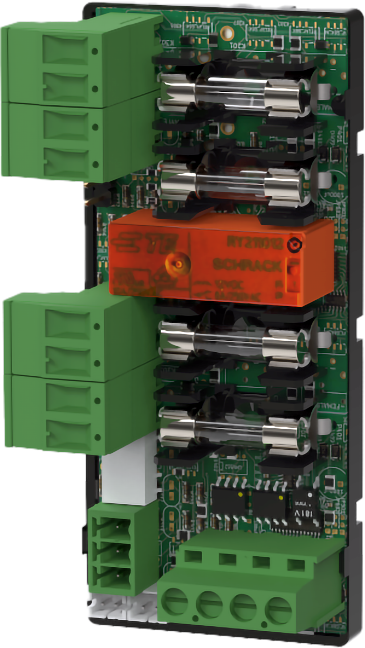
Technical Specifications 2+2 Output module
2+2 Output module is a protection module with four fully protected load outputs, of which two load outputs are prioritized and two are non-prioritized. The card comes mounted in a plastic bracket that is inserted into the battery backup. When ordering, check that the card fits the battery backup card to be installed in.
What does priority / non-priority load mean?
Priority load means that in the event of a power outage (mains failure) the load will be powered on with the reserve power, (batteries),
Non-prioritized load means that in the event of a power cut (mains failure), the load will not be powered further with the reserve power (batteries).
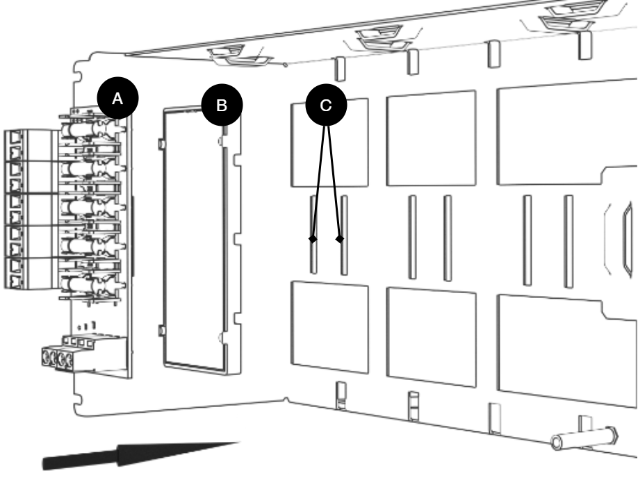
Mounting in battery backup
The card is delivered mounted in it's plastic casing, for easy installation.
If the card has come loose, snap it back into the plastic casing.
Mount the card on any card slot in the enclosure, leave space for cables.
Important
Install the board before screwing on wiring or commissioning.
Letter | Explanation | Comment |
|---|---|---|
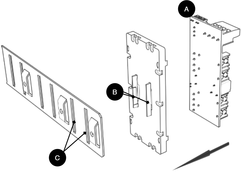
A | Optional card | Optional card comes mounted on plastic housing from factory. Has it come loose? Snap it back on before mounting the card. |
B | Plastic casing | The plastic casing has hooks for attaching slots in the plate. |
C | Place for plastic casing | Slits in sheet metal to snap the plastic bracket. |
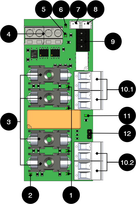
Short description 5 Output module
No | On circuit board | Explanation |
|---|---|---|
1 | D1, D2, D11, D13 | Lights up green when the fuse is full on the output. (Off when fuse is broken). |
2 | D3 | Lights up yellow if prioritized outputs (10.1) are activated. |
3 | F1, F2, F9, F10 | Load securing devices. |
4 | P1 | Incoming 24 V. Use any input. The second input is used when powering additional option cards. Can also be used for external 24 V power supply when replacing the power supply unit on battery backup. |
5 | D29 | Green indicator diode, lights up with a steady green light when all fuses are intact. |
6 | D30 | Red indicator diode, glows with a solid red light when any fuse is broken. |
7 | J11 | Bridging connection for alarms from another option card. |
8 | J12 | Connection of alarm to motherboard. Pin 1 controls non-prioritized output and Pin 0 goes low (0 V) in case of alarm. |
9 | P3:1-3 | Alarm output, NO, COM, NC |
10.1 | P2:1-2 P2:3-4 | Priority load output 1. Priority load output 2. |
10.2 | P2:5-6 P2:7-8 | Unprioritized load output 3. Non-prioritized load output 4. |
11 | D10 | Green indicator diode, lights up green when all outputs are activated. |
12 | JU1 | Control of outputs. Not bridged = Priority (10.1) are activated in battery operation. The factory setting is that the card does not have jumpers on JU1. Bridged = All four outputs are prioritized, i.e. provide 24 V in battery operation. |
Caution
Maximum load per output is 5 A and total maximum load for the entire board is 10 A.
Use the supplied cable
Use the cable that comes with the box to connect the card.
Connect 2+2 Output module to motherboard: CEO3 v2.1
+ and - from load on motherboard are connected to + and - on the option board.
Communication is connected between terminals as the solid line shows.
No | Connections | 2+2 Output module | Motherboard |
|---|---|---|---|
1 | Power supply connection. | P1 | Load output 1 |
2 | Alarm output: connected between NO and Com. | P3:1-2 | JU3 - connect between middle pin and some outer pin. |
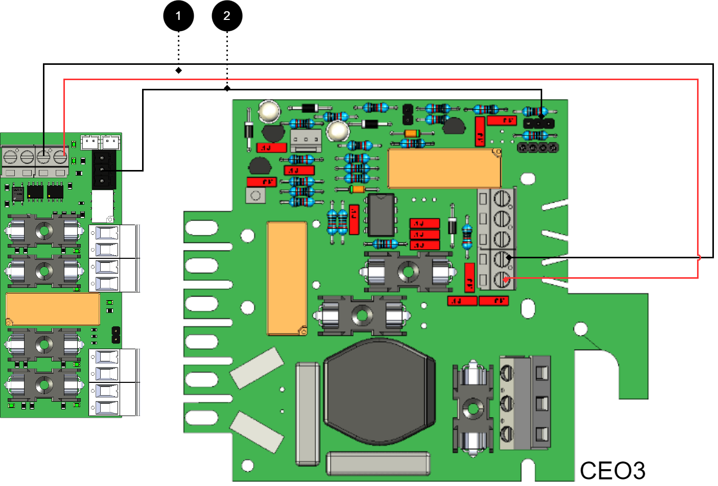
Connect 2+2 Output module to motherboard: CEO3 v5 / CEO-ECO
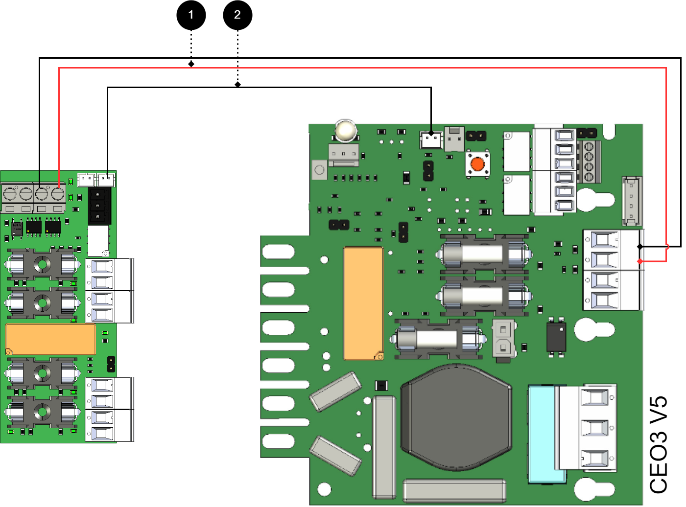
+ and - from load on motherboard are connected to + and - on the option board.
Communication is connected between terminals as the solid line shows.
No | Connections | 2+2 Output module | Motherboard |
|---|---|---|---|
1 | Power supply connection. | P1 | Load output 1 |
2 | Connection to alarm on motherboard or Bridging of alarms to another 5 Output module | J12 J11 | J27 - |
Connect 2+2 Output module to motherboard: NEO3
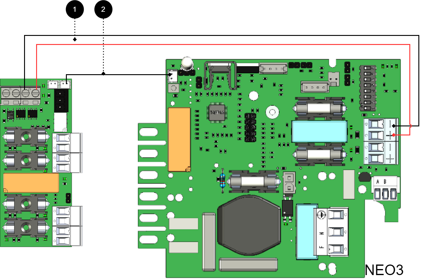
+ and - from load on motherboard are connected to + and - on the option board.
Communication is connected between terminals as the solid line shows.
No | Connections | 2+2 Output module | Motherboard |
|---|---|---|---|
1 | Power supply connection. | P1 | Load output 1 |
2 | Connection to alarm on motherboard. Bridging of alarms to/from additional option cards. | J12 J11 | J5 - |
Connect 2+2 Output module for motherboards: PRO2 v3 15 A and 25 A
No/letter | Circuit board | On circuit board | Explanation |
|---|---|---|---|
A | 2+2 Output module | - | Option card (A). |
B | 2 Output module | - | Connect the power supply (24 V) to the 2+2 Output module (A). |
C | Effect card | - | Available in battery backups 15 A and 25 A. |
D | PRO1 | - | Motherboard in battery backup. |
1 | A and B | P1 | Connect power supply from 2 Output module (B) to 2+2 Output module (A). |
2 | A | J12, J13 | Connect alarm from J12 on 2+2 Ouput module load card. |
3, 4 | - | - | Internal power supply and communication between cards. |
Connect 2+2 Output module for motherboard: PRO1 5 A and 10 A
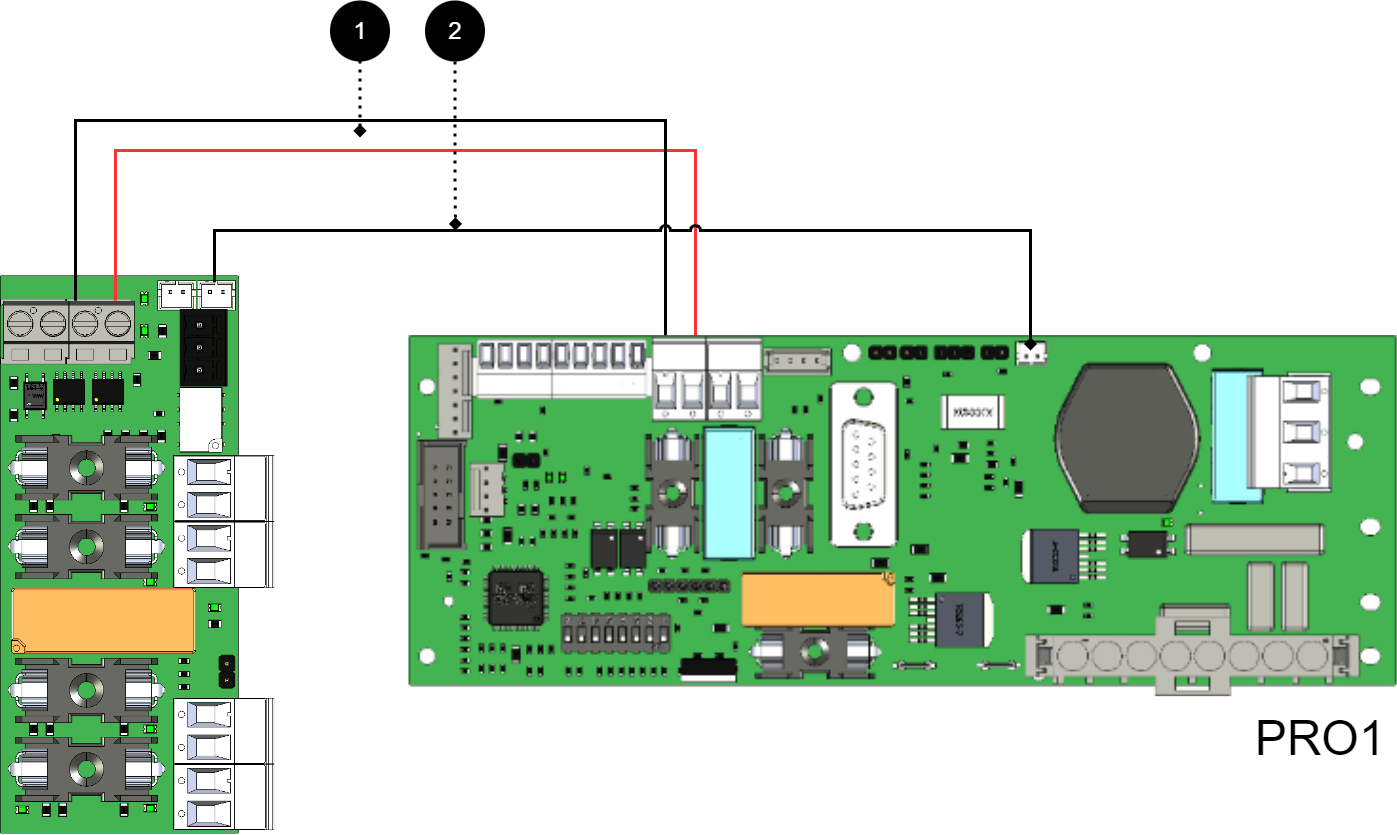
+ and - from load on motherboard are connected to + and - on the option board.
Communication is connected between terminals as the solid line shows.
No | Connections | 2+2 Output module | Motherboard |
|---|---|---|---|
1 | Power supply connection. | P1 | Load output 1 |
2 | Bridging alarm to motherboard. Bridging of alarms from/to additional option cards. | J12 J11 | J13 - |
Connect 2+2 Output module for motherboards: PRO2 v3 5A and 10A
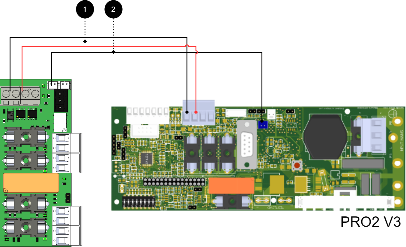
+ and - from load on motherboard are connected to + and - on the option board.
Communication is connected between terminals as the solid line shows.
No | Connections | 2+2 Output module | Motherboard |
|---|---|---|---|
1 | Power supply connection. | P1 | Load output 1 |
2 | Connection to alarm on motherboard. | J12 | J1 |
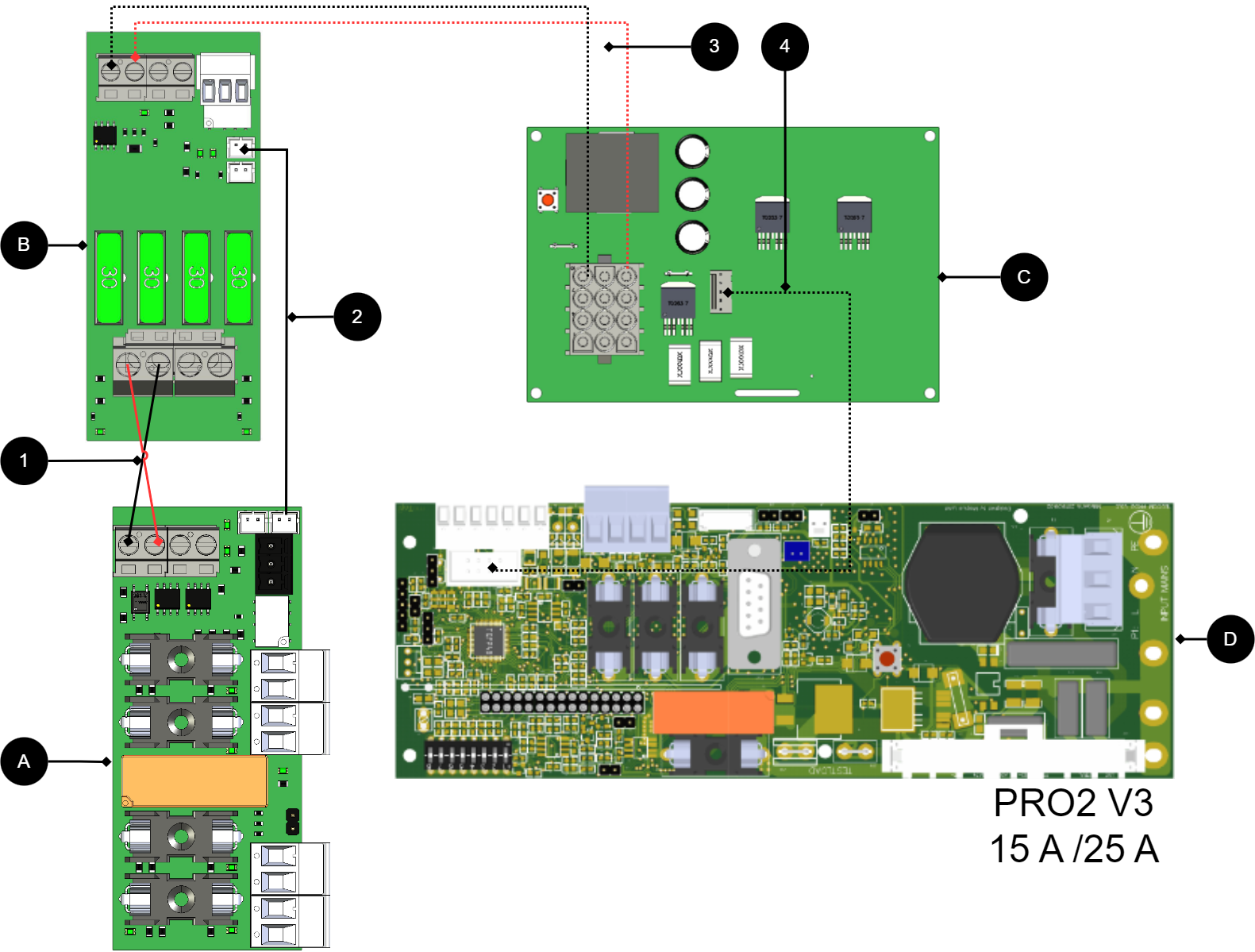
Connect 2+2 Output module for motherboards: PRO2 v3 15 A and 25 A
No/letter | Circuit board | On circuit board | Explanation |
|---|---|---|---|
D | PRO2 v3 | - | Motherboard in battery backup. |
C | Effect card | - | Available in battery backups 15 A and 25 A units. |
1 | A and B | P1 | Connect power supply from 2 output module (B) to 2+2 Ouput module (A). |
2 | A | J12, J1 | Connect alarm from 2+2 Ouput module to load card. |
B | 2 Output modules | - | Connect the power supply (24 V) to the 2+2 Output module (A). |
A | 2+2 Output module | - | Option board (A). |
3, 4 | - | Internal power supply and communication between cards. |
Connect 5 Output module to motherboard: PRO3
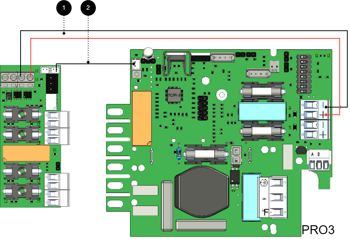
+ and - from load on motherboard are connected to + and - on the option board.
Communication is connected between terminals as the solid line shows.
No | Connections | 2+2 Output module | Motherboard |
|---|---|---|---|
1 | Connecting the power supply. | P1 | Load output 1 |
2 | Connection of alarm on motherboard. Bridging of alarms to/from additional option cards. | J12 J11 | J5 - |
If the card lacks a white (JST) contact or if an alarm is to be given via relay switching
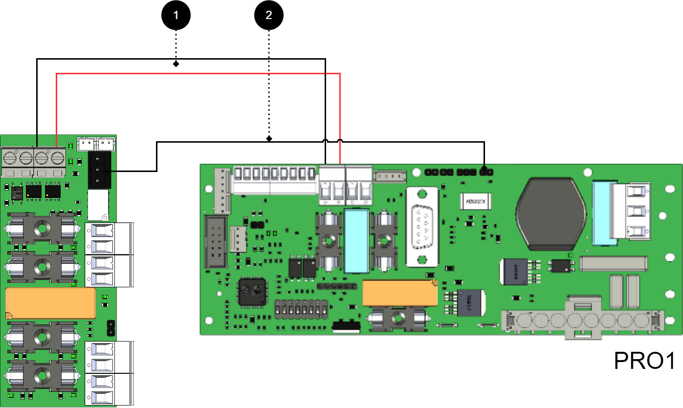
+ and - from load on motherboard are connected to + and - on the option board.
Communication is connected between terminals as the solid line shows.
No | Connections | 2+2 Output module | Motherboard |
|---|---|---|---|
1 | Power supply connection. | P1 | Load output 1 |
2 | Alarm output. | P3:1-3 | J15 |
Connection of additional 2+2 Output module
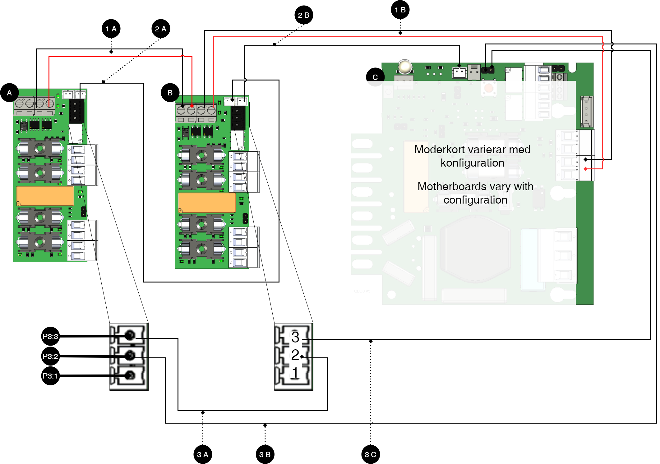
Note
For alarm connection use 2A and 2B for connection of newer devices (after approx. 2018). For older devices (before approx. 2018) use 3A-3C.
Letter / No | On the card | Explanation |
|---|---|---|
A | - | 2+2 Output module. |
B | - | 2+2 Output module. |
C | - | Motherboard, varies with configuration. |
1 A | P1 | Power supply from 1B. |
1 B | P1 | Power supply from C (motherboard). |
2 A | J12 | Bridging of alarms to card B. |
2 B | See table below. | Connection of alarm on C (motherboard) from board A |
3 A | P3:1-3 | Jumper between card A and B. |
3 B | P3:1-3 | Alarm output switches on C (motherboard). |
3C | P3:1-3 | Alarm output is connected to C (motherboard). |
On the card | Explanation |
|---|---|
P3:1 | NO |
P3:2 | Com |
P3:3 | NC |
Technical data - 2+2 Output module
Info | Explanation |
|---|---|
Short name: | 2+2 Output module |
Product description | 2+2 Output module is a hedging module with four fully secured outputs, two of which are prioritized and two are non-prioritized. |
The product fits in | Battery backups with motherboards: PRO1, PRO2, PRO2 V3, PRO3 and NEO3. |
Measure | 85 x 37 mm |
Own consumption | 35 mA |
Tension | 24 V |
Fuses | On exits. |
Indication | Yes, LED on circuit board |
Info | Explanation |
|---|---|
Alarm outputs, number | 1 |
Alarm on alternating relay? (Yes No) | Yes, sum alarm in case of fuse fault |
Alarm output protocol (communication protocol) | - |
Load outputs, number, (of which priority). | 4 (2) |
Voltage at load output | 27.3 V DC |
Voltage limit, upper, on load output | 27.9 V DC |
Voltage limit, lower, on load output. For battery operation and disconnected mains voltage. | 20 V DC |
Priority (always voltage) load outputs (Yes / No) | Yes |
Maximum load, per output | 5 A |
Maximum load, total, (must not be exceeded). | 10 A |
Load output plus (+) secured? (Yes No) | Yes |
Load output minus (-) secured (Yes / No) | No |
Fuses on output | F2A |
Connection to buzzer? (Yes No) | No |
The article number of the manual 350-162
About translation of this document
User manual and other documents are in the original language in Swedish. Other languages are machine translated and not reviewed, errors may occur.
Support
Do you need help with installation or connections? Our support phone is available: Monday-Thursday 08: 00-16: 00 and Fridays 08: 00-15: 00. Telephone support is closed between 11: 30-13: 15.
You will find answers to many questions at: www.milleteknik.se/support
Phone: +46 31-340 02 30
Support is open: Monday-Thursday 08:00-16:00, Fridays 08:00-15:00. Closed 11:30-13:15.
Spare parts
Contacted support for questions about spare parts.
Support after the warranty period
Milleteknik provides support during the life of the product, but no longer than 10 years after the date of purchase. Replacement for an equivalent product may occur if the manufacturer deems that repair is not possible. Costs for support and replacement are added after the warranty period has expired.
Questions about product performance?
Contact sales: 46 31-340 02 30, e-mail: sales@milleteknik.se
Address and contact details
Milleteknik AB |
Ögärdesvägen 8 B |
S-433 30 Partille |
Sweden |
+46 31 340 02 30 |
info@milleteknik.se |
www.milleteknik.com |